Tag Archives: screw screw screw

China Custom-Made PP/PC/ABS Injection Molded Screw Inserts Plastic Insert Molded Parts supplier

Merchandise Description

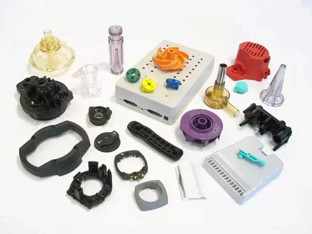
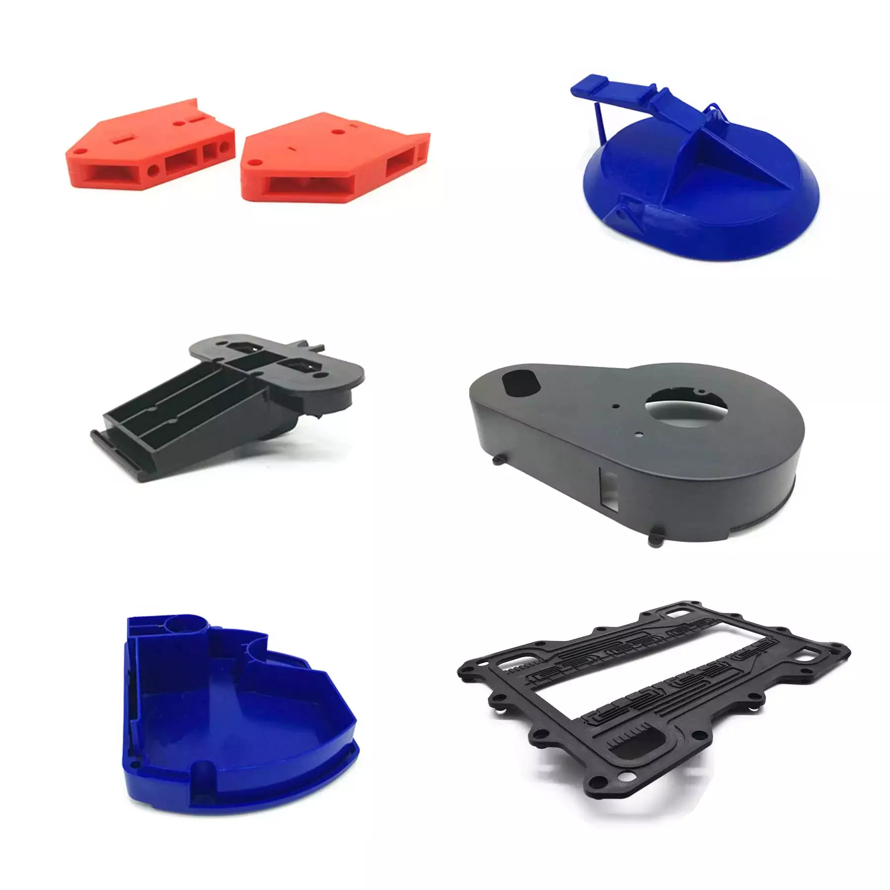
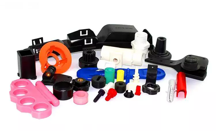
 Custom-created PP/Computer/Abdominal muscles Injection molded Screw Inserts plastic insert molded components


Comprehensive Images


Basic information & policy for our OEM/ODM plastic injection mould:
 

Detailed info for mould steel
Mould materials Hardness Mould existence
P20 HRC 28-33 >300,000 pictures
718 HRC 33-36 >500,000 photographs
H13 HRC >43 >800,000 photographs
2344 HRC >48 >800,000 pictures
S136 HRC 48-fifty two >1,000,000 photographs

Lead Time :

Amount(Sets): 1 – 1 >1
Est. Time(working day): thirty~45 To be negotiated


Description of Ambition Plastic Injection Moulds:
Mould material: forty five#, P20, 718, 2738, NAK80, S136, H13, 1.2344 etc.
Mould foundation: LKM, HASCO, and so on.
Common Ingredient: DME, HASCO, JIS, and many others.
Cavity: One/Multi
Runner: Hot/Chilly
Mould existence: 10,0000~5,000,000shots
Design computer software: UG, PROE, CAD, SolidWorks, and so forth.
Plastic content: PP, Personal computer, PE, PS, PU, Stomach muscles, PVC, PA, POM, PMMA, PET, PPR, and so forth.
Shipping time: forty–60days
Package deal: Wooden Circumstance
Delivery: By Sea 
Technical specs: Is dependent on the customer’s demands
Method Equipment: CNC, High-Speed Carver, EDM, Wire Reduce, Driller, Grinder, fly cutter, and so on.

Ambition Mould Trade Procedure:
 

1. Quotation According to the sample, drawing, and particular requirements.
two. Dialogue Mold material, cavity amount, cost, runner, payment, etc.
three. S/C Signature Approval for all the products
four. Progress Pay out fifty% by T/T
five. Solution Style Checking We verify the item layout. If some place is not perfect, or can not be done on the mould, we will ship the client the report.
six. Mould Layout We make mould design and style on the foundation of verified solution designs and deliver them to the buyer for confirmation.
seven. Mould Tooling We start to make mildew after the mildew design and style verified
eight. Mold Processing Ship report to buyer when each 7 days
nine. Mould Tests Send out trial samples and attempt-out reviews to the buyer for confirmation
10. Mould Modification According to the customer’s opinions
11. Stability Settlement fifty% by T/T right after the customer approves the trial sample and mould high quality.
12. Supply Supply by sea or air. The forwarder can be designated by your side.


Company info:

Started in 2571, We are focused to supplying our consumers with the greatest level of plastic mildew manufacturing & injection molding services. 

We always insist on the idea of buyer gratification and characteristics. We have established some examples of consumers in distinct nations around the world for new customer referrals. We truly hope that we can build a long-term business relationship with CZPT cooperation with you.

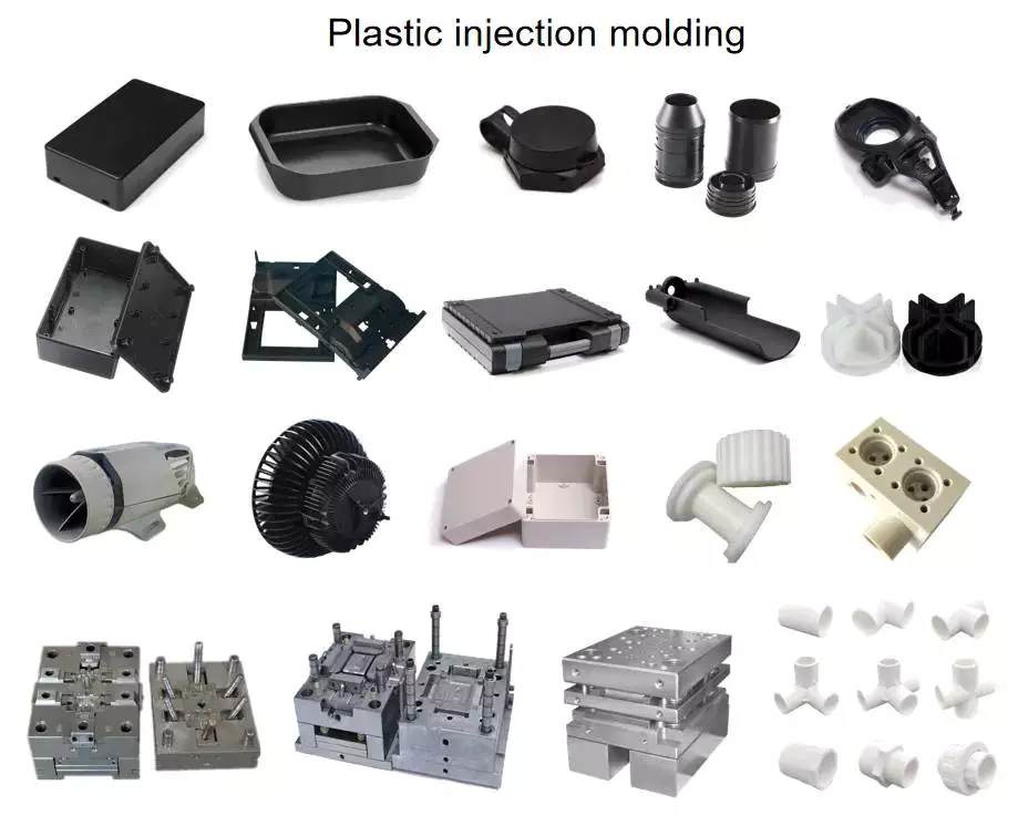
We can make all types of plastic injection mould which includes automotive part moulds, cosmetic element moulds, medical portion molds, residence equipment moulds, electronic portion moulds and so on.

We have abundant knowledge in creating custom-made plastic injection mould. Send out me the inquiry with the drawing and necessity (steel raw content, cavity no. and so on) for mould, and I will reply to you in 24 several hours and quotation for you inside of 2 working times. 


Why Choose Us:
 

Greatest style, competitive price
More than 10 years’ Rich expertise in this area
Specialist in design & making plastic mould
1 quit solution
On-time supply
Greatest following-sale service
Specialized in all sorts of plastic injection moulds

Packaging & Transport:


FAQ:
 

1. Q: I have an idea for a new product, but I don’t know if it can be manufactured. Can you help?
 A: Yes! We are always happy to work with potential customers to evaluate the technical feasibility of your idea or design and we can advise on materials, tooling, and likely set-up costs.

two. Q: What are the advantages of obtaining my parts manufactured locally?
 A: We can offer quick reaction times to any changes in specification, batch size, or material. We can ship small or large quantities anywhere in North America, and Europe overnight to accommodate unforeseen changes in demand.

3. Q: My components have already been developed in CAD. Can you use the drawings?
 A: Yes! DWG, DXF, IGES, Solid works and STP, X_T          files can all be used to generate quotes, models, and mold tools – this can save time and money in producing
 your parts.

4. Q: Can I test my idea/component before committing to mold tool manufacture?
 A: Yes, we can use CAD drawings to make Prototype models for design and functional evaluations or industry tests.

five. Q: What type of plastic is best for my design/ingredient?
 A: Materials selection depends on the application of your design and the environment in which it will function. We will be happy to discuss the alternatives and suggest the best material.


six. Q: What type of mould tool do I need?
 A: Mould tools can be either a single cavity (one part at a time) or multi-cavity (2,4, 8, or 16 parts at a time). Single-cavity tools are generally used for small quantities, up to 10,000 parts per year whereas multi-cavity tools are for larger quantities. We can look at your projected annual requirements and recommend the 
best tooling option for you.


7. Q: Okay, I’ve decided to go ahead with my project. How long will it take to get my parts?
   A: It can take 3 to 6 weeks to have the mould tool manufactured depending on the part’s complexity, dimensions, and the number of impressions/ cavities (single or multiple). After we receive your final approval on the tool’s preliminary design, you can expect delivery of T1 parts within 3-6 weeks. And throughout the mildew creating process, mildew builds Weekly Update will be presented to you every week for your better comprehending of the manufacturing development in our workshop.


US $1,000-20,000
/ Set
|
1 Set

(Min. Order)

###

Warranty: 3 Years
Shaping Mode: Injection Mould
Surface Finish Process: Polishing
Mould Cavity: Multi Cavity
Plastic Material: ABS
Process Combination Type: Single-Process Mode

###

Samples:
US$ 0.5/Piece
1 Piece(Min.Order)

|
Request Sample

###

Customization:

###

Detailed info for mould steel
Mould material Hardness Mould life
P20 HRC 28-33 >300,000 shots
718 HRC 33-36 >500,000 shots
H13 HRC >43 >800,000 shots
2344 HRC >48 >800,000 shots
S136 HRC 48-52 >1,000,000 shots

###

Quantity(Sets): 1 – 1 >1
Est. Time(day): 30~45 To be negotiated

###

Description of Ambition Plastic Injection Moulds:
Mould material: 45#, P20, 718, 2738, NAK80, S136, H13, 1.2344 etc.
Mould base: LKM, HASCO, etc.
Standard Component: DME, HASCO, JIS, etc.
Cavity: Single/Multi
Runner: Hot/Cold
Mould life: 10,0000~5,000,000shots
Design software: UG, PROE, CAD, SolidWorks, etc.
Plastic material: PP, PC, PE, PS, PU, ABS, PVC, PA, POM, PMMA, PET, PPR, etc.
Delivery time: 40–60days
Package: Wooden Case
Delivery: By Sea 
Specifications: Depends on the customer’s requirements
Process Machine: CNC, High-Speed Carver, EDM, Wire Cut, Driller, Grinder, fly cutter, etc.

###

1. Quote According to the sample, drawing, and specific requirements.
2. Discussion Mold material, cavity number, price, runner, payment, etc.
3. S/C Signature Approval for all the items
4. Advance Pay 50% by T/T
5. Product Design Checking We check the product design. If some position is not perfect, or can not be done on the mould, we will send the customer the report.
6. Mould Design We make mould design on the basis of confirmed product designs and send them to the customer for confirmation.
7. Mold Tooling We start to make mold after the mold design confirmed
8. Mold Processing Send report to customer once each week
9. Mold Testing Send trial samples and try-out reports to the customer for confirmation
10. Mold Modification According to the customer’s feedback
11. Balance Settlement 50% by T/T after the customer approves the trial sample and mould quality.
12. Delivery Delivery by sea or air. The forwarder can be designated by your side.

###

Best design, competitive price
Over 10 years’ Rich experience in this field
Professional in design & making plastic mould
One stop solution
On-time delivery
Best after-sale service
Specialized in all kinds of plastic injection moulds

Factors to Consider When Converting a Design to Injection Molding

When considering injection molding for your design, there are several things you should consider. These factors include design, material selection, process, and reliability. In addition, you should consider the price of each part. The average cost per injection molded part is between $1 and $5. If you want to reduce your costs and improve your production cycle, look into converting your design to injection molding.

Design considerations for injection molded parts

Injection molded parttInjection molded parts must meet certain design considerations to ensure quality and precision. Design considerations include proper material choice, process control, and tool design. In addition, designers must consider the tolerance ranges for the parts to be produced. These tolerances will differ from molder to molder, and designers should discuss their specific needs with their molders before they begin production. Designers must also consider possible revisions to the mold, such as making the part more or less tighter.
When designing injection molded parts, the designer should consider the thickness of each wall. This will minimize stresses that may arise due to uneven wall thickness. Parts with uneven wall thickness can develop sink marks, voids, and molded-in stresses. This can result in longer production time and increased cost. Moreover, irregular wall thickness can restrict material flow. To minimize these problems, designers should make the transitions between the different thicknesses smooth.
Another important design consideration is the use of bosses in injection molded parts. Bosses are typically used as points of assembly and attachment in injection molded parts. Bosses are cylindrical projections with holes for threaded inserts and other fastening hardware. Injection molded parts with bosses are generally able to accommodate multiple threaded inserts without stripping. These inserts are also durable and enable several cycles of assembly.
The thickness of the walls is another important consideration when designing injection molded parts. The thickness of walls will determine many key characteristics of the part. Careful consideration of this feature will prevent expensive mold modifications and delays. The nominal wall thickness should be determined based on the functional requirements of the part. Likewise, the minimum wall thickness should be set based on acceptable stress. If the walls are too thin, air will collect between them and compromise the functional performance of the part.

Material selection

Selecting the right material for your injection molded parts is an important part of the process. While there are many options, there are also many factors to consider. For instance, what kind of end product are you producing? Whether it’s a consumer part for your home or a complex part for the aerospace industry, you’ll need the right material for the job.
There are literally hundreds or thousands of types of plastic materials available for injection molding. One of the most common types is ABS, a polymer that has a high degree of structural strength and low cost. Another popular choice is polycarbonate, which offers excellent heat resistance and transparency. Alternatively, you can opt for Ultem, a high performance plastic that’s commonly used in medical and aerospace applications.
The process of designing plastic products involves a combination of art and science. The goal of this process is to create a high-quality product that meets the expectations of consumers. By doing this, you’ll reduce production costs and increase profits. It’s not an easy process, but it’s well worth the effort.
Injection molding is an efficient and versatile method of manufacturing medical devices. It can be done in high volumes and with high flexibility. In addition to this, it also offers a broad range of materials. This is important when your parts need to be made of different materials with unique physical properties. For example, if you’re producing toys, you’ll want to use Acrylonitrile Butadiene Styrene (ABS). ABS is also a great option for medical applications because it can withstand the high temperatures and pressures of medical environments.
When choosing plastic injection molding materials, keep in mind the weight and stiffness of the material. Some applications require hard plastics, while others require softer materials. In addition, the material’s flexibility will determine how much you can bend it.

Process

Injection molded parttInjection molding is a process in which plastic parts are formed by pressing melt into a mold. The process takes place in two stages. During the first step, the material is injected and heated, while the second stage is when the mold is opened and the part ejected. The part is then finished and ready for use.
The material used in injection molding is made from a variety of polymers. Common polymers include nylon, elastomers, and thermoplastics. Since 1995, the number of materials used in injection molding has increased by 750 percent. Some materials are newly developed while others are alloys of previously-developed materials. The selection of material primarily depends on the strength and function required by the final part. Also, the cost of the material is a critical factor.
The design of custom components for the molding process should be carried out by a skilled industrial designer. There are a number of design guidelines for plastic parts, which should be followed carefully to achieve high quality and dimensional accuracy. Failure to follow these guidelines can lead to undesirable results. Therefore, it is crucial to specify specific requirements for the parts before the process begins.
The process is reliable and highly repeatable, making it ideal for large-scale production. Injection molding also allows for the creation of multi-cavity injection mold parts, which can create several parts in one cycle. Other advantages of the injection molding process include low labor costs, minimal scrap losses, and low post-mold finishing costs.
Before beginning the full production run, technicians perform a trial run. In this test, they insert a small shot weight in the mould. Then, they apply a small holding pressure and increase the holding time until the gate freezes. Then, they weigh the part to check if it is right.

Reliability

Injection-molded parts are subject to a variety of defects. One of the most common is unwanted deformation. This may happen when the temperature of the mold is too high or there is not enough plastic injected into the mold. Another problem is millidiopter range distortion. This distortion is invisible to the naked eye, and cannot be detected by manual inspection. Regardless of the cause, preventing unwanted deformations is critical for the long-term performance of the part.
The process of creating a custom mould for a plastic component requires great skill. Creating a mould that is perfectly suited to the product is important, because a good mould is crucial in avoiding potential defects. Traditionally, this process relied on the skill of a toolmaker and trial-and-error methods. This slows down the process and increases the cost of production.
Another factor contributing to injection molded parts’ reliability is the high level of repeatability. Injection molding is ideal for high volume production, because parts are easily re-molded. However, the process can be prone to failure if there is no quality control. While most injection-molded parts will last for a long time, parts that are prone to wear will eventually fail.
Besides high level of consistency and reliability, injection-molded parts are also eco-friendly. Unlike other manufacturing methods, the injection molding process produces little to no waste. Much of the plastic left behind in the process can be recycled, making it a green alternative. Another benefit of this manufacturing method is automation, which helps reduce production costs. Overall, injection molding is a highly reliable and consistent product.
Injection molding requires precise measurements and a 3-D model. It is also important to check for wall uniformity and draft angles. Properly-designed parts can avoid deformations. If the wall thickness is too low, support ribs can be used. Proper draft angles are important to ensure that the part can be removed easily from the mold.

Cost

Injection molded parttThe cost of injection molded parts depends on many factors, including the complexity of the part and the mold design. Simpler designs, fewer CAD steps and simpler processes can help companies minimize costs. Another factor that affects the cost of injection molded parts is the geometry of the part. In general, complex geometries require more design work and tooling time. Additionally, thicker walls require more material than thin ones, which raises the cost of the part.
The amount of plastic used in the mold is also a key factor. Injection molding requires large quantities of material, so parts that are larger will require a larger mold. Larger parts are also more complex, so these require more detailed molds. A mold maker will be able to advise you on how to design your part to cut down on costs.
The next major factor affecting the cost of injection molded parts is the material of the mold. Most injection molds are made of steel, but the type and grade of steel used is important. Additionally, tight tolerances require molds with virtually wear-free interior cavities. Hence, higher-grade steel is required.
Another factor affecting the cost of injection molded parts is the price of mold tools. Depending on the size and complexity of the part, the cost of molding tools can vary from $10,000 to several hundred thousand dollars. Injection molding tooling is an integral part of the entire process and can add up to a significant portion of the overall cost of the part.
Draft angles are another factor that affects the cost of injection molded parts. A draft is an important design element as it allows for easy part separation and removal from the mold. Without a draft, it would be very difficult to remove a part after injection.
China Custom-Made PP/PC/ABS Injection Molded Screw Inserts Plastic Insert Molded Parts     supplier China Custom-Made PP/PC/ABS Injection Molded Screw Inserts Plastic Insert Molded Parts     supplier
editor by czh 2023-03-28

China Custom-Made PP/PC/ABS Injection Molded Screw Inserts Plastic Insert Molded Parts with Good quality

Merchandise Description

 Custom-produced PP/Computer/Stomach muscles Injection molded Screw Inserts plastic insert molded elements


Thorough Photographs


Common information & plan for our OEM/ODM plastic injection mould:
 

Detailed details for mould metal
Mould substance Hardness Mould daily life
P20 HRC 28-33 >300,000 shots
718 HRC 33-36 >500,000 shots
H13 HRC >43 >800,000 pictures
2344 HRC >48 >800,000 pictures
S136 HRC forty eight-52 >1,000,000 shots

Guide Time :

Amount(Sets): 1 – 1 >1
Est. Time(working day): 30~45 To be negotiated


Description of Ambition Plastic Injection Moulds:
Mould materials: 45#, P20, 718, 2738, NAK80, S136, H13, 1.2344 etc.
Mould base: LKM, HASCO, and so forth.
Regular Part: DME, HASCO, JIS, and so on.
Cavity: One/Multi
Runner: Sizzling/Chilly
Mould existence: ten,0000~5,000,000shots
Design and style application: UG, PROE, CAD, SolidWorks, and so forth.
Plastic material: PP, Computer, PE, PS, PU, Stomach muscles, PVC, PA, POM, PMMA, PET, PPR, and so forth.
Shipping and delivery time: forty–60days
Package deal: Wood Case
Supply: By Sea 
Specifications: Relies upon on the customer’s needs
Process Machine: CNC, Large-Speed Carver, EDM, Wire Cut, Driller, Grinder, fly cutter, and so on.

Ambition Mould Trade Approach:
 

1. Estimate According to the sample, drawing, and distinct needs.
two. Dialogue Mold material, cavity quantity, price, runner, payment, and many others.
3. S/C Signature Approval for all the items
4. Progress Spend 50% by T/T
five. Item Design Checking We examine the merchandise design. If some placement is not perfect, or can not be accomplished on the mould, we will ship the buyer the report.
six. Mould Layout We make mould layout on the foundation of confirmed item designs and send them to the consumer for affirmation.
7. Mold Tooling We begin to make mold following the mold style verified
8. Mould Processing Ship report to customer when each and every 7 days
9. Mildew Tests Send demo samples and try-out reports to the buyer for affirmation
ten. Mold Modification According to the customer’s comments
11. Stability Settlement 50% by T/T following the client approves the trial sample and mould good quality.
twelve. Shipping Shipping and delivery by sea or air. The forwarder can be specified by your facet.


Firm data:

Founded in 2571, We are focused to offering our consumers with the greatest degree of plastic mildew production & injection molding solutions. 

We often insist on the notion of client gratification and qualities. We have established some illustrations of consumers in different international locations for new buyer referrals. We genuinely hope that we can develop a lengthy-phrase business connection with CZPT cooperation with you.

We can make all sorts of plastic injection mould which includes automotive part moulds, cosmetic part moulds, healthcare part molds, house appliance moulds, digital element moulds and so on.

We have prosperous knowledge in creating personalized plastic injection mould. Send me the inquiry with the drawing and prerequisite (steel raw content, cavity no. and so forth) for mould, and I will reply to you within 24 several hours and quote for you inside 2 working days. 


Why Choose Us:
 

Greatest layout, competitive price
More than 10 years’ Wealthy expertise in this area
Skilled in design and style & making plastic mould
1 stop resolution
On-time shipping and delivery
Greatest soon after-sale service
Specialised in all sorts of plastic injection moulds

Packaging & Delivery:


FAQ:
 

1. Q: I have an idea for a new product, but I don’t know if it can be manufactured. Can you help?
 A: Yes! We are always happy to work with potential customers to evaluate the technical feasibility of your idea or design and we can advise on materials, tooling, and likely set-up costs.

two. Q: What are the advantages of getting my parts manufactured locally?
 A: We can offer quick reaction times to any changes in specification, batch size, or material. We can ship small or large quantities anywhere in North The united states, and Europe overnight to accommodate unforeseen changes in demand.

three. Q: My components have already been developed in CAD. Can you use the drawings?
 A: Yes! DWG, DXF, IGES, Solid works and STP, X_T          files can all be used to generate quotes, models, and mold tools – this can save time and money in producing
 your parts.

4. Q: Can I test my idea/component before committing to mold tool manufacture?
 A: Indeed, we can use CAD drawings to make Prototype models for design and functional evaluations or industry exams.

five. Q: What type of plastic is best for my design/element?
 A: Materials selection depends on the application of your design and the environment in which it will function. We will be happy to discuss the alternatives and suggest the best material.


six. Q: What type of mould tool do I need?
 A: Mould tools can be either a single cavity (one part at a time) or multi-cavity (2,4, 8, or 16 parts at a time). Single-cavity tools are generally used for small quantities, up to 10,000 parts per year whereas multi-cavity tools are for larger quantities. We can look at your projected annual requirements and recommend the 
best tooling option for you.


7. Q: Alright, I’ve decided to go ahead with my project. How long will it take to get my parts?
   A: It can take 3 to 6 weeks to have the mould tool manufactured depending on the part’s complexity, measurement, and the number of impressions/ cavities (single or multiple). After we receive your final approval on the tool’s preliminary design and style, you can expect delivery of T1 parts within 3-6 weeks. And in the course of the mould building method, mildew builds Weekly Update will be supplied to you each 7 days for your greater comprehending of the production development in our workshop.


US $1,000-20,000
/ Set
|
1 Set

(Min. Order)

###

Warranty: 3 Years
Shaping Mode: Injection Mould
Surface Finish Process: Polishing
Mould Cavity: Multi Cavity
Plastic Material: ABS
Process Combination Type: Single-Process Mode

###

Samples:
US$ 0.5/Piece
1 Piece(Min.Order)

|
Request Sample

###

Customization:

###

Detailed info for mould steel
Mould material Hardness Mould life
P20 HRC 28-33 >300,000 shots
718 HRC 33-36 >500,000 shots
H13 HRC >43 >800,000 shots
2344 HRC >48 >800,000 shots
S136 HRC 48-52 >1,000,000 shots

###

Quantity(Sets): 1 – 1 >1
Est. Time(day): 30~45 To be negotiated

###

Description of Ambition Plastic Injection Moulds:
Mould material: 45#, P20, 718, 2738, NAK80, S136, H13, 1.2344 etc.
Mould base: LKM, HASCO, etc.
Standard Component: DME, HASCO, JIS, etc.
Cavity: Single/Multi
Runner: Hot/Cold
Mould life: 10,0000~5,000,000shots
Design software: UG, PROE, CAD, SolidWorks, etc.
Plastic material: PP, PC, PE, PS, PU, ABS, PVC, PA, POM, PMMA, PET, PPR, etc.
Delivery time: 40–60days
Package: Wooden Case
Delivery: By Sea 
Specifications: Depends on the customer’s requirements
Process Machine: CNC, High-Speed Carver, EDM, Wire Cut, Driller, Grinder, fly cutter, etc.

###

1. Quote According to the sample, drawing, and specific requirements.
2. Discussion Mold material, cavity number, price, runner, payment, etc.
3. S/C Signature Approval for all the items
4. Advance Pay 50% by T/T
5. Product Design Checking We check the product design. If some position is not perfect, or can not be done on the mould, we will send the customer the report.
6. Mould Design We make mould design on the basis of confirmed product designs and send them to the customer for confirmation.
7. Mold Tooling We start to make mold after the mold design confirmed
8. Mold Processing Send report to customer once each week
9. Mold Testing Send trial samples and try-out reports to the customer for confirmation
10. Mold Modification According to the customer’s feedback
11. Balance Settlement 50% by T/T after the customer approves the trial sample and mould quality.
12. Delivery Delivery by sea or air. The forwarder can be designated by your side.

###

Best design, competitive price
Over 10 years’ Rich experience in this field
Professional in design & making plastic mould
One stop solution
On-time delivery
Best after-sale service
Specialized in all kinds of plastic injection moulds

Benefits of Injection Molded Parts in Design

Injection molded parts are manufactured from a variety of plastics. You can order samples of your desired product or download CAD drawings free of charge. For more information, visit our product catalog. There are numerous benefits of using injection molded products in your designs. Here are some of them. Injection molded products are cost-effective and highly customizable.

Design for manufacturability

Injection molded parttDesign for manufacturability (DFMA) is an important part of the design process for injection-molded parts. This process helps to minimize costs and streamline the production process. It also helps in the prevention of problems during the manufacturing process. The process involves several steps that include part geometry, location of critical surfaces, material selection, and dimensioning. It is also crucial to consider the colors and tolerances, which can help to minimize scrap rates.
Design for manufacturability is a vital early stage in the development process to ensure that the product is cost-effective and repeatable. It begins with a thorough understanding of the purpose for which the part is intended. The design process should take into account every aspect of the part, including the material section, tool design, and the production process.
DFM includes guidelines to ensure that the design meets the manufacturing requirements. These guidelines can include good manufacturing practices, as well as good design principles. Good design focuses on the quantity and quality of parts, as well as the complexity of their surfaces and tolerances. The process also focuses on mechanical and optical properties.
Injection molding design for manufacturability can save resources and time. It also reduces the costs of assembly. An injection molder conducts a detailed analysis of these design elements before starting the tooling process. This is not a standalone principle; it should be used in conjunction with other design optimization techniques.
Ideally, a product should be designed for optimum manufacture. This means that it should not have too many parts, or too few. To minimize this, the designer should choose a model that is easy to mold. Also, a design that does not require too many machine operations and minimizes risks.

Plastics used in injection molding

Injection molded partt
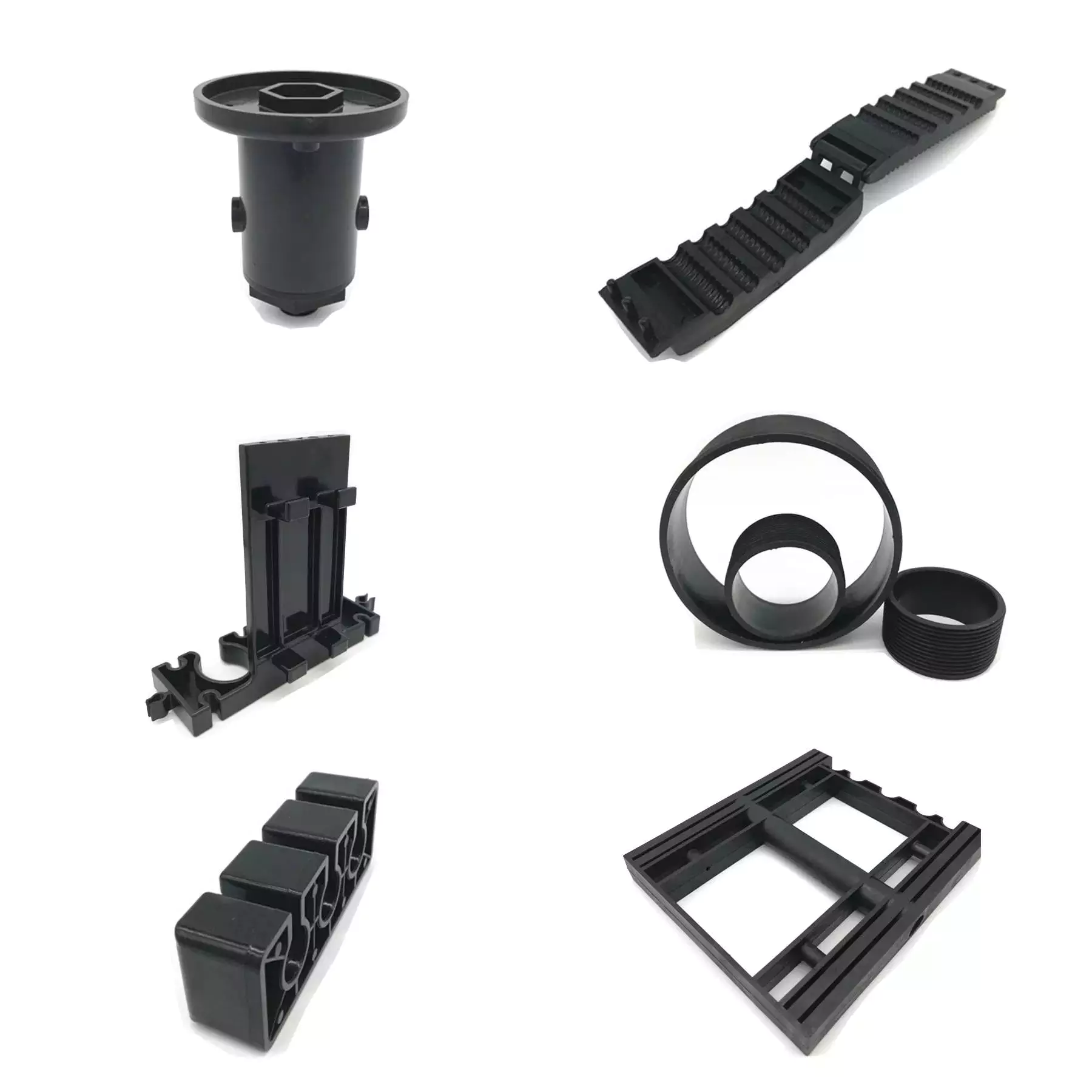
Injection molding is a very versatile process that uses various types of plastic polymers. These plastics are extremely flexible and can be molded to take on any shape, color, and finish. They can also be customized to contain design elements, text, and safety instructions. Plastics are also lightweight, easily recycled, and can be hermetically sealed to prevent moisture from getting into the product.
Plastics are categorized according to their properties, which can be helpful in selecting the right plastic for a particular application. Different materials have different degrees of hardness, which is important when it comes to molding applications. Some are harder than others, while others are more flexible. Plastics are ranked according to their Shore hardness, which was developed by CZPT.
Polystyrene is one of the most common plastics used in injection molding. However, it has a few disadvantages. While it is a good choice for simple products that do not require high strength and are prone to breakage, it is not ideal for items that need to be resistant to heat and pressure.
While many types of plastics are used in injection molding, choosing the right material is very important. The right material can make a big difference in the performance of your product and the cost of your product. Make sure to talk with your injection molding supplier to determine which plastic is right for your project. You should look for a plastic with a high impact rating and FDA approval.
Another commonly used plastic is PMMA, or polystyrene. This plastic is affordable and has a glass-like finish. It is often used for food and beverage packaging and can be easily recycled. This material is also used in textiles.Characteristics of polypropylene
Polypropylene injection molded parts offer an array of benefits, including a high degree of rigidity, excellent thermal stability, low coefficient of friction, and chemical resistance. These plastics are available in two main types, homopolymers and copolymers. Both types offer superior hardness and tensile strength. However, the material does not have the same fire-resistance as PE plastics.
Polypropylene is a colorless, odorless, crystalline solid. It is highly resistant to a variety of chemicals and is shatter-resistant. Its properties make it a great choice for many industrial applications, including packaging and containers for liquids. The material is also highly durable and can last for a very long time without breaking. In addition, it does not absorb or retain moisture, making it ideal for outdoor and laboratory applications.
Polypropylene is widely used for injection molding, and its low cost, flexibility, and resistance to chemical attack make it a popular choice. This material is also a great electrical insulator and has excellent thermal expansion coefficient. However, it is not biodegradable. Luckily, it can be recycled.
During the molding process, the temperature of the mold is a significant factor. Its morphology is related to the temperature and flow field, and a clear correlation between the two factors is essential. If you can control the temperature and flow, you can optimize your manufacturing process and eliminate costly trial-and-error procedures.
Polypropylene is an excellent electrical insulator and has a high dielectric coefficient. It can also be sterilized and resist high temperatures. Although it is less rigid than polyethylene, it is a good choice for applications where electrical insulation is necessary.

Texture of injection molded parts

Injection molded parttTexture design is a common feature of injection molded parts, which helps to raise the perceived value of the vehicle. While traditional manufacturing processes can produce limited textures, additive manufacturing allows for infinite designs. For example, a design that looks like a wood grain pattern may be printed on an aluminum car part.
Texture is important because it can improve the strength of the part and enhance its adhesion to other surfaces. Moreover, textured parts can resist damage from contact and fingerprints. This makes them more durable and a good option for further molding operations. Injection molding processes usually follow a set of standards from the Society of Plastics Industry, which define different types of surface finishes.
Textured plastic injection molded parts may have various types of surfaces, including wood grain, leather, sand, or stipple. Choosing the right surface texture is crucial for enhancing the appearance of the part, but it must also be compatible with its function. Different materials have different chemical and physical properties, which can influence the type of texture. Moreover, the melting temperature of the material is important for its surface finish. The additives used in the process can also have an impact on the surface finish.
Texture can also vary between manufacturers and types of components. Some textures are flat, while others are rough. The top row corresponds to A3 and B4 in flatness, while the bottom row shows rough surfaces. These rough surfaces may damage sensitive testing equipment. However, some textures may have near equivalence with each other, namely SPI D-3 and MT-11020.
The type of texture that is applied to injection molded parts can affect the minimum draft angle required for the parts to be ejected. Parts with light texture tend to be smoother than parts with heavy textures, while parts with heavy textures require a higher draft angle. The draft angle for heavy textures should be between five and 12 degrees. It is best to consider this early in the design process and consult with the injection molder to get a good idea of the necessary draft angles.
China Custom-Made PP/PC/ABS Injection Molded Screw Inserts Plastic Insert Molded Parts     with Good quality China Custom-Made PP/PC/ABS Injection Molded Screw Inserts Plastic Insert Molded Parts     with Good quality
editor by czh 2023-03-27

China Good quality Aluminum Housing Screw Conveyor RV Series Horizontal Shaft Plastic Textile Machine Gear Box Nmrv Worm Orthogonal Gear Reducer near me supplier

Product Description

Aluminum Housing Screw Conveyor RV Sequence Horizontal Shaft Plastic Textile Machine Equipment Box Nmrv Worm Orthogonal Equipment Reducer

1. The broad and extensive variety of N series for industrial programs
two. Reduced-velocity shaft design and style: Cylindrical with important, splined, hollow with shrink disc or splined hollow shaft
3. Rigid and exact nodular solid iron casing
4. Reduced sound managing, large producing good quality normal
5. High and dependable functionality, load capacity and low-pace shaft bearing


You should click here for a lot more types!


Our Companies

With all our routines DNV-ISO 9001, SGS -accredited, we stand for prime-quality services. Entrusting your gearboxes to the treatment of our Services.

Assist defend your gearbox from use and grinding, SGR gearbox converts torque reliably and effi­ciently.
We customize our CZPT planetary gear units, double enveloping worm gearbox, helical gear motor, modular layout helical gear unit, worm gearbox, cycloidal gearbox etc to suit your software and fulfill your wants. 

These attributes enable a dependable and protected support lifestyle of over two hundred 000 operational hrs. 

Our buyers have been positioning their CZPT in CZPT gear units given that 1997. Much more than 500 000 equipment models of our gearbox are in use reliably around the globe, in a lot of situations under very severe circumstances.


Relevant Goods


For much more reducers and mechanical equipment, you should click here to view


How to Figure out the Top quality of a Worm Shaft

There are several rewards of a worm shaft. It is less difficult to manufacture, as it does not call for handbook straightening. Between these positive aspects are relieve of routine maintenance, decreased price, and simplicity of installation. In addition, this kind of shaft is much less vulnerable to hurt thanks to guide straightening. This post will go over the different factors that decide the top quality of a worm shaft. It also discusses the Dedendum, Root diameter, and Wear load capability.
worm shaft

Root diameter

There are various options when deciding on worm gearing. The assortment depends on the transmission used and generation choices. The basic profile parameters of worm gearing are explained in the expert and agency literature and are utilised in geometry calculations. The chosen variant is then transferred to the primary calculation. Nonetheless, you have to consider into account the energy parameters and the gear ratios for the calculation to be correct. Listed here are some guidelines to choose the proper worm gearing.
The root diameter of a worm equipment is calculated from the middle of its pitch. Its pitch diameter is a standardized price that is decided from its force angle at the stage of zero gearing correction. The worm equipment pitch diameter is calculated by including the worm’s dimension to the nominal middle length. When defining the worm equipment pitch, you have to maintain in brain that the root diameter of the worm shaft have to be smaller sized than the pitch diameter.
Worm gearing demands teeth to evenly distribute the dress in. For this, the tooth side of the worm must be convex in the standard and centre-line sections. The shape of the tooth, referred to as the evolvent profile, resembles a helical equipment. Typically, the root diameter of a worm gear is more than a quarter inch. However, a 50 percent-inch variation is satisfactory.
Another way to estimate the gearing performance of a worm shaft is by seeking at the worm’s sacrificial wheel. A sacrificial wheel is softer than the worm, so most put on and tear will happen on the wheel. Oil investigation reports of worm gearing models almost usually show a higher copper and iron ratio, suggesting that the worm’s gearing is ineffective.

Dedendum

The dedendum of a worm shaft refers to the radial length of its tooth. The pitch diameter and the small diameter figure out the dedendum. In an imperial system, the pitch diameter is referred to as the diametral pitch. Other parameters consist of the encounter width and fillet radius. Confront width describes the width of the gear wheel with no hub projections. Fillet radius measures the radius on the idea of the cutter and varieties a trochoidal curve.
The diameter of a hub is calculated at its outer diameter, and its projection is the length the hub extends outside of the equipment experience. There are two sorts of addendum teeth, one particular with short-addendum enamel and the other with long-addendum enamel. The gears themselves have a keyway (a groove machined into the shaft and bore). A key is equipped into the keyway, which fits into the shaft.
Worm gears transmit movement from two shafts that are not parallel, and have a line-toothed style. The pitch circle has two or far more arcs, and the worm and sprocket are supported by anti-friction roller bearings. Worm gears have substantial friction and dress in on the tooth tooth and restraining surfaces. If you would like to know far more about worm gears, consider a seem at the definitions beneath.
worm shaft

CZPT’s whirling approach

Whirling process is a present day production strategy that is changing thread milling and hobbing processes. It has been in a position to decrease production fees and lead times while generating precision gear worms. In addition, it has decreased the need for thread grinding and floor roughness. It also reduces thread rolling. This is far more on how CZPT whirling approach works.
The whirling method on the worm shaft can be utilised for creating a range of screw sorts and worms. They can make screw shafts with outer diameters of up to 2.5 inches. In contrast to other whirling procedures, the worm shaft is sacrificial, and the procedure does not demand machining. A vortex tube is utilised to provide chilled compressed air to the slicing level. If essential, oil is also included to the combine.
One more method for hardening a worm shaft is referred to as induction hardening. The approach is a large-frequency electrical procedure that induces eddy currents in metallic objects. The increased the frequency, the more surface area warmth it generates. With induction heating, you can software the heating procedure to harden only certain regions of the worm shaft. The duration of the worm shaft is usually shortened.
Worm gears supply many benefits more than common gear sets. If used accurately, they are reputable and very successful. By following appropriate set up recommendations and lubrication tips, worm gears can supply the very same dependable provider as any other kind of gear established. The write-up by Ray Thibault, a mechanical engineer at the University of Virginia, is an outstanding guidebook to lubrication on worm gears.

Use load potential

The put on load capacity of a worm shaft is a key parameter when figuring out the effectiveness of a gearbox. Worms can be made with various gear ratios, and the layout of the worm shaft must replicate this. To establish the dress in load capability of a worm, you can check out its geometry. Worms are normally made with teeth ranging from one particular to four and up to twelve. Choosing the proper number of teeth relies upon on a number of aspects, including the optimisation demands, this kind of as performance, excess weight, and centre-line length.
Worm equipment tooth forces increase with enhanced electricity density, creating the worm shaft to deflect a lot more. This minimizes its use load capacity, lowers effectiveness, and raises NVH actions. Advancements in lubricants and bronze materials, mixed with better manufacturing quality, have enabled the steady boost in energy density. People three aspects merged will figure out the wear load capability of your worm equipment. It is vital to think about all 3 factors ahead of picking the appropriate equipment tooth profile.
The minimal amount of equipment teeth in a equipment relies upon on the stress angle at zero gearing correction. The worm diameter d1 is arbitrary and depends on a known module price, mx or mn. Worms and gears with different ratios can be interchanged. An involute helicoid assures appropriate make contact with and form, and provides increased precision and life. The involute helicoid worm is also a key ingredient of a gear.
Worm gears are a kind of historic equipment. A cylindrical worm engages with a toothed wheel to lessen rotational velocity. Worm gears are also employed as prime movers. If you’re seeking for a gearbox, it could be a very good option. If you happen to be contemplating a worm gear, be positive to examine its load ability and lubrication specifications.
worm shaft

NVH behavior

The NVH behavior of a worm shaft is decided using the finite aspect approach. The simulation parameters are described employing the finite element approach and experimental worm shafts are in comparison to the simulation outcomes. The benefits present that a large deviation exists amongst the simulated and experimental values. In addition, the bending stiffness of the worm shaft is extremely dependent on the geometry of the worm gear toothings. Hence, an sufficient design and style for a worm equipment toothing can support reduce the NVH (sound-vibration) actions of the worm shaft.
To calculate the worm shaft’s NVH behavior, the principal axes of instant of inertia are the diameter of the worm and the number of threads. This will affect the angle among the worm tooth and the efficient length of each and every tooth. The distance between the primary axes of the worm shaft and the worm gear is the analytical equivalent bending diameter. The diameter of the worm gear is referred to as its successful diameter.
The elevated power density of a worm equipment benefits in improved forces performing on the corresponding worm gear tooth. This leads to a corresponding increase in deflection of the worm equipment, which negatively affects its efficiency and put on load potential. In addition, the rising energy density demands improved production top quality. The ongoing advancement in bronze resources and lubricants has also facilitated the continued boost in electricity density.
The toothing of the worm gears establishes the worm shaft deflection. The bending stiffness of the worm gear toothing is also calculated by employing a tooth-dependent bending stiffness. The deflection is then transformed into a stiffness worth by making use of the stiffness of the personal sections of the worm shaft. As shown in determine 5, a transverse section of a two-threaded worm is proven in the figure.

China Good quality Aluminum Housing Screw Conveyor RV Series Horizontal Shaft Plastic Textile Machine Gear Box Nmrv Worm Orthogonal Gear Reducer     near me supplier China Good quality Aluminum Housing Screw Conveyor RV Series Horizontal Shaft Plastic Textile Machine Gear Box Nmrv Worm Orthogonal Gear Reducer     near me supplier

China best Quality Manual Worm Gear Table Lift, Manual Screw Jack 5ton Manufacturer near me manufacturer

Product Description

We are substantial quality guide worm equipment table lift, guide screw jack 5ton companies and suppliers in China. All handbook worm gear desk carry, handbook screw jack 5ton are available in load capacity 1/4 ton, 1/2 ton, 1 ton, 2 ton, 2.5 ton, 3 ton, 5 ton, 10 ton, fifteen ton and 20 ton, large load more substantial than 20 ton ability, hand-operated screw jack is not suggested. They are best options for apps exactly where electrical power or power generators is inconvenient or hazardous, mild bodyweight, reduced duty cycle, reduced target price and short journey length. If have to be not backdriving, a self locking device screw jack with handwheel is the greatest option. If large speed ball screw jack with handwheel, locking mechanisms need to be considered.

Solid Iron Handwheel Descriptions
Cast iron handwheel diameter 125mm, 160mm, 200mm, 250mm, 320mm and 400mm, more substantial diameter handwheel is obtainable, you should seek advice from CZPT sales. The suggest screw jack .25 ton, .5 ton, 1 ton, 2 ton, 2.5 ton, 5 ton, 10 ton, fifteen ton, twenty ton capacities are available in matching cast iron handwheel for hand-operation software.

Aluminum Handwheel with Folding Handle Descriptions
Aluminum handwheel diameter 80mm, 100mm, 125mm, 160mm and 200mm. The advocate screw jack .twenty five ton, .5 ton, 1 ton, 2 ton, 2.5 ton, 5 ton capacities are offered in matching aluminum handwheel for hand-procedure application.

In buy to exact position display of the travel size, the worm shaft adds a digital place indicator which measures the rotation and show a corresponding position in a counter window. There are 3 sizes situation indicators: 04 collection position indicator 4 numbers with 14mm hollow shaft, 09 sequence placement indicator 5 figures with 20mm hollow shaft, 10 series situation indicator 5 quantities with 25mm or 30mm hollow shaft. Be aware: inapplicable motorized screw jacks.


Packing Images & Shipping
Shipping and delivery:
1. CZPT freight: seaport to seaport, value terms CIF, FOB, EXW, CFR etc.
2. Air freight: airport to airport, cost conditions EXW, CRF etc.
3. Air Express: DHL, FEDEX, UPS, TNT.
Packaging: 
Powerful Exporting Plywood Situations (Global Exporting Regular Wooden Material with Cost-free Fumigation)

Our Benefits
1. Worldwide regular supplies for All CZPT brand merchandise. We insist on selecting brand name suppliers to supply the higher quality uncooked supplies to control the making approach. Optimization continually the production processes, inspecting in each url and controlling production site.
2. 100% quality assured with double high quality inspections. The good quality inspection by good quality inspectors from processing to concluded goods as the 1st time. Prior to packing, the corresponding product sales engineers need to inspect the orders subsequent the paper drawings, get portions and special markings in the invoice or income contracts as the next time. 
3. 100% safety transportation. Packing with robust standard export plywood cases supplies (totally free fumigation), inner packing with epe foams to avert goods swaying and outer packing with iron sheets and fasteners to fasten the deals.
four. Internationl sales engineers have skilled understanding and abilities on our normal goods and service. They have sufficient potential to solve the basic technical dilemma immediately no matter what by phone, online chat, experience to experience communications.
five. All the standard goods with 2d CAD Drawings (PDF, DWG and DXF formats), and 3D CAD Designs (Step, STP, Model, IGS, PRT and CATParT formats).
six. Custom style accessible, OEM support accessible, Free engineering suggestions, Cost-free rates accessible and Client label obtainable.
7. Inspection equipments incorporate motor with inverter drive method, peak adjustmemt motorized lifting technique, coordinate measuring devices, exterior micrometers, inside micrometers, depth calipers, vernier calipers, digital calipers, hardness testers, digital sound meters, industrial infrared thermometers, digital velocity measuring devices, digital multimeters, and large precision clamp digital ammeter and many others. 
8. Processing with CZPT superior devices this sort of as CNC gear hobbing equipment, CNC flank grinding machines, CNC cylindrical grinding machines, multi-axis CNC milling machines, CNC lathes and others equipments. 

Finished Initiatives
one. Theatrical answers phase and orchestra platform lifts projects. Clients are from France, Australia, Netherlands, United Kingdom, Spain and Canada. 
2. Hydroelectric energy station projects and water conservancy tasks. Clients are from Vietnam, Australia, Malaysia, Russian Federation, Nepal, Pakistan, Belgium, United States and United Kingdom. 
3. Aircraft routine maintenance platforms and docking techniques tasks. Consumers are from Pakistan, Singapore and United Arab Emirates.  
four. Photo voltaic panel tracking system tasks. Clients are from Spain, India and Canada. 
five. Bolted steel storage tanks and silos lifting answers. Buyers are from South Africa, United States, Mexico, Russian Federation, Brazil and Vietnam. 
6. Dish antenna elevation and azimuth positioning initiatives. Clients are from Singapore, Malaysia and United States. 
7. Railway wagon projects. Consumers are from South Africa. 
8. CZPT can generation strains. Consumers are from Netherlands, United States, Thailand and Indonesia. 
9. Metal factories creation lines. Consumers are from Iran, United States and Turkey. 
10. Steady PU sandwich panel generation strains. Buyers are from Thailand and United Kingdom. 

Our Products List
one. Manual screw jacks, Electric screw jacks.
2. Screw Jacks Collection: JT sequence CZPT screw jacks, JTC sequence cubic screw jacks, JTW collection device screw jacks, JTM collection worm screw jacks, JTB sequence ball screw jacks, JTD collection cubic ball screw jacks, JSS collection stainless steel screw jacks, JTS collection bevel equipment screw jacks, Non-common series screw jacks. 
3. Bevel Gearboxes Series: JT sequence bevel gearboxes, JTP collection cubic bevel gearboxes, JTA sequence aluminum bevel gearboxes. 
four. Lifting Programs and Methods Equipment: two-jacks methods, a few-jacks techniques, 4-jacks systems, six-jacks systems, eight-jacks techniques.. Components go over couplings, CZPT joints, cardan shafts, connecting shafts, electric powered motors, geared motors and reducers, hand wheel with crank handles, pillow block bearings, flange block bearings, rod finish bearings, quit nuts, limit switches, protection nut, journey nuts, linear shafts and bearings, linear guides and bearings, telescopic spring addresses, bellows boot, protective tube, trunnion adapter plates, trunnion mounting brackets, motor flanges, rotary encoders, potentiometers, frequency inverters and position indicators etc.
five. Linear Actuators Collection: Parallel linear actuators with 3-stage AC motors, Inline linear actuators with 3-section AC motors, 
six. Gearmotors and Reducers Series: helical gearmotors R sequence, helical bevel gearmotors K series, parallel shaft helical gearmotors F sequence, helical worm gearmotors S collection, little AC gear motor collection and worm equipment motor reducer series.

Our Customers’ Nations around the world
1. American Countries: United States, Mexico, Canada, Chile, Xihu (West Lake) Dis.by means of, Brazil, Colombia, Dominican Republic, Honduras, Costa Rica, Panama, Puerto Rico, Jamaica, Trinidad and Tobago, Aruba, Argentina, Peru, Venezuela.
2. European International locations: Russia, Germany, Turkey, France, United Kingdom, Italy, Spain, Ukraine, Poland, Romania, Netherlands, Belgium, Greece, Czech Republic, Portugal, Sweden, Hungary, Belarus, Austria, Switzerland, Bulgaria, Denmark, Finland, Slovakia, Norway, Ireland, Croatia, Ga, Armenia, Lithuania, Slovenia, Estonia, Cyprus, Luxembourg, Iceland.
three. Asian Nations around the world: Malaysia, Indonesia, Singapore, Pakistan, Philippines, Vietnam, United Arab Emirates, Thailand, Saudi Arabia, Iran, Turkey, India, Nepal, Yemen, ZheJiang , Sri Lanka, Israel, Jordan, Kuwait, Qatar.
4. Oceanian Nations around the world: Australia, New Zealand, Fiji.
five. African Countries: South Africa, Egypt, Ethiopia, Nigeria, Kenya, Tanzania.

Speak to Details
HangZhou CZPT Business Co.,Ltd (VAT No.: 9144190007026567X3, registered Money 500000CNY) is a major producer and supplier in China for screw jacks (mechanical actuators), bevel gearboxes, lifting methods, linear actuators, gearmotors and speed reducers, and other individuals linear movement and energy transmission goods. We are Alibaba, Produced-In-China and SGS (Serial NO.: QIP-ASI192186) audited maker and provider. We also have a rigorous top quality program, with senior engineers, experienced experienced staff and practiced income groups, we constantly give the large high quality equipments to meet the consumers electro-mechanical actuation, lifting and positioning needs. CZPT Industry ensures good quality, trustworthiness, efficiency and benefit for present day demanding industrial purposes. 
Site 1: http://screw-jacks
Internet site 2:

How to Choose a Worm Shaft and Equipment For Your Venture

You will find out about axial pitch PX and tooth parameters for a Worm Shaft twenty and Gear 22. Detailed data on these two parts will assist you pick a appropriate Worm Shaft. Go through on to find out far more….and get your fingers on the most superior gearbox at any time designed! Below are some ideas for selecting a Worm Shaft and Gear for your task!…and a couple of issues to hold in head.
worm shaft

Equipment 22

The tooth profile of Gear 22 on Worm Shaft twenty differs from that of a traditional gear. This is since the enamel of Gear 22 are concave, enabling for far better interaction with the threads of the worm shaft twenty. The worm’s direct angle triggers the worm to self-lock, preventing reverse motion. However, this self-locking system is not fully trusted. Worm gears are utilised in quite a few industrial programs, from elevators to fishing reels and automotive electricity steering.
The new gear is mounted on a shaft that is secured in an oil seal. To install a new equipment, you initial need to get rid of the old gear. Up coming, you need to unscrew the two bolts that maintain the gear on to the shaft. Up coming, you must take away the bearing carrier from the output shaft. Once the worm equipment is eliminated, you need to have to unscrew the retaining ring. Right after that, set up the bearing cones and the shaft spacer. Make sure that the shaft is tightened effectively, but do not more than-tighten the plug.
To avert untimely failures, use the appropriate lubricant for the type of worm gear. A substantial viscosity oil is necessary for the sliding motion of worm gears. In two-thirds of apps, lubricants have been insufficient. If the worm is evenly loaded, a lower-viscosity oil may be enough. Or else, a large-viscosity oil is necessary to maintain the worm gears in great problem.
One more alternative is to vary the number of tooth all around the gear 22 to reduce the output shaft’s pace. This can be completed by placing a distinct ratio (for instance, five or ten moments the motor’s pace) and modifying the worm’s dedendum appropriately. This procedure will minimize the output shaft’s pace to the wanted amount. The worm’s dedendum must be adapted to the desired axial pitch.

Worm Shaft twenty

When deciding on a worm gear, consider the pursuing items to think about. These are high-functionality, minimal-sounds gears. They are resilient, reduced-temperature, and prolonged-lasting. Worm gears are extensively employed in quite a few industries and have numerous advantages. Outlined beneath are just some of their positive aspects. Go through on for far more information. Worm gears can be hard to maintain, but with proper routine maintenance, they can be really trustworthy.
The worm shaft is configured to be supported in a body 24. The dimensions of the body 24 is decided by the center length in between the worm shaft 20 and the output shaft sixteen. The worm shaft and gear 22 may possibly not appear in speak to or interfere with a single yet another if they are not configured appropriately. For these causes, suitable assembly is essential. However, if the worm shaft 20 is not correctly put in, the assembly will not function.
Another critical consideration is the worm materials. Some worm gears have brass wheels, which may possibly result in corrosion in the worm. In addition, sulfur-phosphorous EP equipment oil activates on the brass wheel. These supplies can cause significant decline of load area. Worm gears need to be installed with high-good quality lubricant to prevent these difficulties. There is also a need to pick a material that is high-viscosity and has minimal friction.
Pace reducers can incorporate several distinct worm shafts, and each and every speed reducer will require various ratios. In this situation, the pace reducer company can offer various worm shafts with diverse thread patterns. The various thread patterns will correspond to various equipment ratios. No matter of the gear ratio, each and every worm shaft is made from a blank with the desired thread. It will not be tough to discover a single that fits your requirements.
worm shaft

Gear 22’s axial pitch PX

The axial pitch of a worm equipment is calculated by using the nominal centre length and the Addendum Issue, a consistent. The Middle Length is the length from the middle of the gear to the worm wheel. The worm wheel pitch is also named the worm pitch. Equally the dimension and the pitch diameter are taken into thought when calculating the axial pitch PX for a Equipment 22.
The axial pitch, or direct angle, of a worm equipment determines how efficient it is. The larger the direct angle, the considerably less productive the gear. Guide angles are directly relevant to the worm gear’s load ability. In particular, the angle of the direct is proportional to the size of the stress area on the worm wheel enamel. A worm gear’s load capability is right proportional to the quantity of root bending anxiety released by cantilever action. A worm with a guide angle of g is almost equivalent to a helical equipment with a helix angle of ninety deg.
In the existing invention, an enhanced strategy of producing worm shafts is explained. The method involves identifying the desired axial pitch PX for each reduction ratio and body size. The axial pitch is recognized by a strategy of manufacturing a worm shaft that has a thread that corresponds to the sought after gear ratio. A gear is a rotating assembly of elements that are made up of teeth and a worm.
In addition to the axial pitch, a worm gear’s shaft can also be produced from various materials. The material utilized for the gear’s worms is an critical thought in its choice. Worm gears are normally made of metal, which is more powerful and corrosion-resistant than other resources. They also require lubrication and might have floor enamel to lessen friction. In addition, worm gears are usually quieter than other gears.

Equipment 22’s tooth parameters

A study of Gear 22’s tooth parameters uncovered that the worm shaft’s deflection depends on a variety of elements. The parameters of the worm equipment had been varied to account for the worm gear measurement, stress angle, and size element. In addition, the number of worm threads was changed. These parameters are different based on the ISO/TS 14521 reference gear. This study validates the developed numerical calculation design utilizing experimental benefits from Lutz and FEM calculations of worm gear shafts.
Employing the benefits from the Lutz test, we can get the deflection of the worm shaft employing the calculation approach of ISO/TS 14521 and DIN 3996. The calculation of the bending diameter of a worm shaft in accordance to the formulation presented in AGMA 6022 and DIN 3996 demonstrate a excellent correlation with take a look at outcomes. Nonetheless, the calculation of the worm shaft using the root diameter of the worm makes use of a different parameter to compute the equal bending diameter.
The bending stiffness of a worm shaft is calculated via a finite component design (FEM). Using a FEM simulation, the deflection of a worm shaft can be calculated from its toothing parameters. The deflection can be deemed for a complete gearbox program as stiffness of the worm toothing is regarded as. And ultimately, based on this examine, a correction issue is designed.
For an ideal worm gear, the number of thread starts off is proportional to the dimensions of the worm. The worm’s diameter and toothing aspect are calculated from Equation 9, which is a formulation for the worm gear’s root inertia. The distance in between the principal axes and the worm shaft is established by Equation 14.
worm shaft

Equipment 22’s deflection

To research the effect of toothing parameters on the deflection of a worm shaft, we employed a finite element approach. The parameters regarded are tooth top, strain angle, size aspect, and variety of worm threads. Every single of these parameters has a different influence on worm shaft bending. Desk 1 exhibits the parameter variants for a reference equipment (Equipment 22) and a different toothing product. The worm gear dimension and variety of threads determine the deflection of the worm shaft.
The calculation technique of ISO/TS 14521 is based mostly on the boundary circumstances of the Lutz examination setup. This approach calculates the deflection of the worm shaft using the finite factor approach. The experimentally calculated shafts were when compared to the simulation benefits. The examination results and the correction factor have been in comparison to confirm that the calculated deflection is equivalent to the calculated deflection.
The FEM analysis suggests the effect of tooth parameters on worm shaft bending. Gear 22’s deflection on Worm Shaft can be defined by the ratio of tooth drive to mass. The ratio of worm tooth drive to mass determines the torque. The ratio between the two parameters is the rotational velocity. The ratio of worm gear tooth forces to worm shaft mass establishes the deflection of worm gears. The deflection of a worm gear has an impact on worm shaft bending potential, effectiveness, and NVH. The steady growth of electrical power density has been accomplished via developments in bronze materials, lubricants, and producing quality.
The primary axes of instant of inertia are indicated with the letters A-N. The three-dimensional graphs are similar for the 7-threaded and one-threaded worms. The diagrams also display the axial profiles of every single gear. In addition, the principal axes of minute of inertia are indicated by a white cross.

China best Quality Manual Worm Gear Table Lift, Manual Screw Jack 5ton Manufacturer     near me manufacturer China best Quality Manual Worm Gear Table Lift, Manual Screw Jack 5ton Manufacturer     near me manufacturer