Product Description
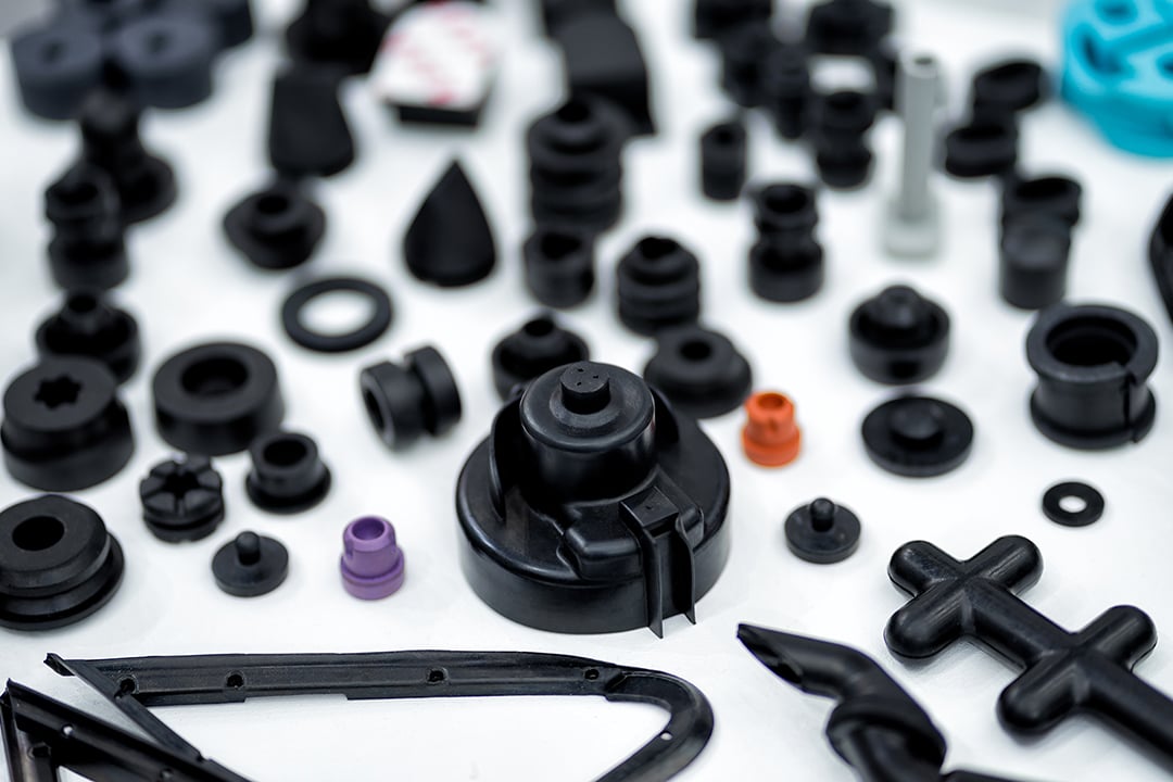
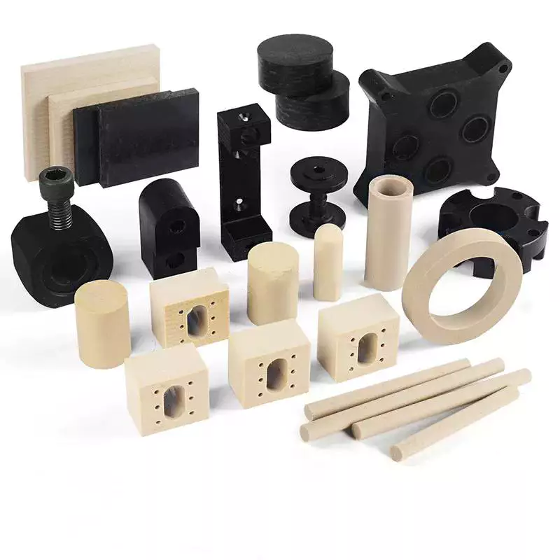
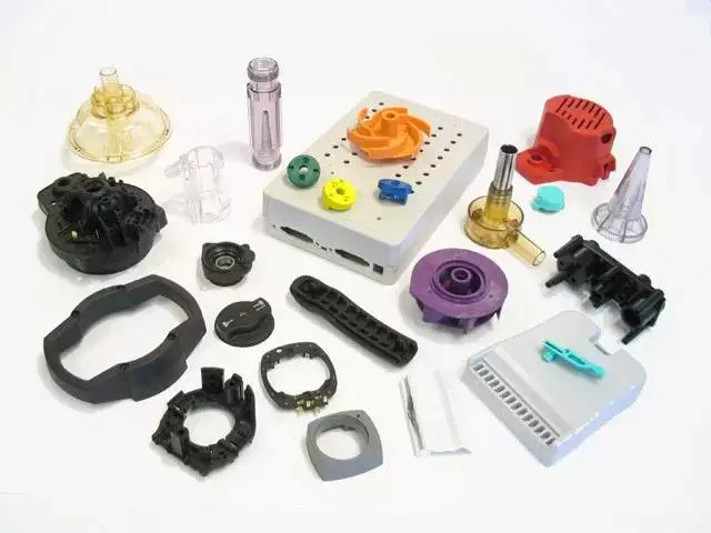
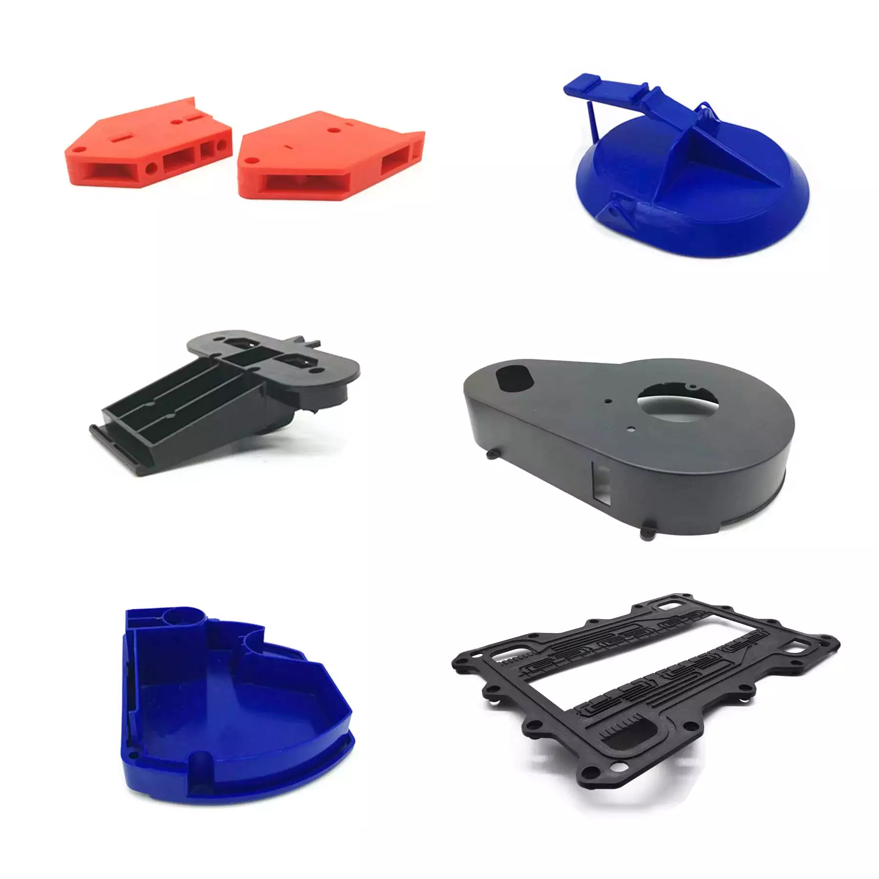
[Custom oem injection molded plastic rubber machinery parts]
Company Information
Our company is located in HangZhou City,ZheJiang , the world’s manufacturing capital. We are dedicated to the production of CNC milling & turning parts and high-precision mold components, machined parts and all kinds of Knives & Blades according to the requirements of customers from different industries. Products are mainly exported to Europe, USA and Japan, and obtains favor reputation from customers.
We will always adhere to the values of “Details, Focusing, Principal, Leading” and the business philosophy of “Constantly Improvement, Precision Dedication” to serve the customers more and better and to create value for customers.
OUR SERVICES
We specialize in CNC Machined Parts,Precision Injection Mold Parts, Plasic Injection Moulding, and Machining all kinds of Knives and Blades.
OUR INDUSTRIES
We serve in the industries of Automobile, Mobile Phone, Computer and Medical Parts, Home Appliances, Led Lights, Electrotechnical Application, Aerospace, Consumer Electronics, Watches, Agriculture, Food Packaging & Processing and Archery, Telescope,UAV,Robot,etc.
Products Description
| Material: | PMMA,PC,PP,PEEK,PU,PA,POM,PE,UPE,etc. |
| Color: | White,black,green,nature,blue,yellow,etc. |
| Diameter: | 5-1000mm,or customized. |
| Shape: | According to your drawings. |
| Certification: | ISO9001,SGS,Test Report,RoSH. |
| Advantage | One stop procurement. |
| Packing | Plastic bags,Cartons,Wodden case,Pallet,Container,ect. |
| Mold Processing | CNC machining,Drilling, EDM,and then testing. |
| File Formats | Solid Works(STEP), Pro/Engineer, AutoCAD(DXF,DWG), PDF,etc. |
| Negotiations: | Quality,material,price,payment,delivery time item and so on |
| R&D: | According to customer’s requirements,we could design and improve the 3D moulding files. |
| We will send our customers the 3D files for confirmation.Once the customers approved,then we will start to build the mold. | |
| Sample confirm: | We can send the trial sample to customers for approval, If the customers are not satisfied it, then we will modify the mould. |
| Other | 24 hours instant and comfortable customer service. |
| Shipping status notification during delivery. | |
| Regular notification of new styles & hot selling styles. |
Logistic
/* March 10, 2571 17:59:20 */!function(){function s(e,r){var a,o={};try{e&&e.split(“,”).forEach(function(e,t){e&&(a=e.match(/(.*?):(.*)$/))&&1
| Shaping Mode: | Injection Mould |
|---|---|
| Surface Finish Process: | Polishing |
| Mould Cavity: | Multi Cavity |
| Plastic Material: | ABS |
| Application: | Car, Household Appliances, Furniture, Commodity, Electronic, Home Use |
| Design Software: | Pro-E |
| Samples: |
US$ 1/Piece
1 Piece(Min.Order) | |
|---|
| Customization: |
Available
|
|
|---|
What factors influence the design and tooling of injection molded parts for specific applications?
Several factors play a crucial role in influencing the design and tooling of injection molded parts for specific applications. The following are key factors that need to be considered:
1. Functionality and Performance Requirements:
The intended functionality and performance requirements of the part heavily influence its design and tooling. Factors such as strength, durability, dimensional accuracy, chemical resistance, and temperature resistance are essential considerations. The part’s design must be optimized to meet these requirements while ensuring proper functionality and performance in its intended application.
2. Material Selection:
The choice of material for injection molding depends on the specific application and its requirements. Different materials have varying properties, such as strength, flexibility, heat resistance, chemical resistance, and electrical conductivity. The material selection influences the design and tooling considerations, as the part’s geometry and structure must be compatible with the selected material’s properties.
3. Part Complexity and Geometry:
The complexity and geometry of the part significantly impact its design and tooling. Complex parts with intricate features, undercuts, thin walls, or varying thicknesses may require specialized tooling and mold designs. The part’s geometry must be carefully considered to ensure proper mold filling, cooling, ejection, and dimensional stability during the injection molding process.
4. Manufacturing Cost and Efficiency:
The design and tooling of injection molded parts are also influenced by manufacturing cost and efficiency considerations. Design features that reduce material usage, minimize cycle time, and optimize the use of the injection molding machine can help lower production costs. Efficient tooling designs, such as multi-cavity molds or family molds, can increase productivity and reduce per-part costs.
5. Moldability and Mold Design:
The moldability of the part, including factors like draft angles, wall thickness, and gate location, affects the mold design. The part should be designed to facilitate proper flow of molten plastic during injection, ensure uniform cooling, and allow for easy part ejection. The tooling design, such as the number of cavities, gate design, and cooling system, is influenced by the part’s moldability requirements.
6. Regulatory and Industry Standards:
Specific applications, especially in industries like automotive, aerospace, and medical, may have regulatory and industry standards that influence the design and tooling considerations. Compliance with these standards regarding materials, dimensions, safety, and performance requirements is essential and may impact the design choices and tooling specifications.
7. Assembly and Integration:
If the injection molded part needs to be assembled or integrated with other components or systems, the design and tooling must consider the assembly process and requirements. Features such as snap fits, interlocking mechanisms, or specific mating surfacescan be incorporated into the part’s design to facilitate efficient assembly and integration.
8. Aesthetics and Branding:
In consumer products and certain industries, the aesthetic appearance and branding of the part may be crucial. Design considerations such as surface finish, texture, color, and the inclusion of logos or branding elements may be important factors that influence the design and tooling decisions.
Overall, the design and tooling of injection molded parts for specific applications are influenced by a combination of functional requirements, material considerations, part complexity, manufacturing cost and efficiency, moldability, regulatory standards, assembly requirements, and aesthetic factors. It is essential to carefully consider these factors to achieve optimal part design and successful injection molding production.
How do innovations and advancements in injection molding technology influence part design and production?
Innovations and advancements in injection molding technology have a significant influence on part design and production. These advancements introduce new capabilities, enhance process efficiency, improve part quality, and expand the range of applications for injection molded parts. Here’s a detailed explanation of how innovations and advancements in injection molding technology influence part design and production:
Design Freedom:
Advancements in injection molding technology have expanded the design freedom for part designers. With the introduction of advanced software tools, such as computer-aided design (CAD) and simulation software, designers can create complex geometries, intricate features, and highly optimized designs. The use of 3D modeling and simulation allows for the identification and resolution of potential design issues before manufacturing. This design freedom enables the production of innovative and highly functional parts that were previously challenging or impossible to manufacture using conventional techniques.
Improved Precision and Accuracy:
Innovations in injection molding technology have led to improved precision and accuracy in part production. High-precision molds, advanced control systems, and closed-loop feedback mechanisms ensure precise control over the molding process variables, such as temperature, pressure, and cooling. This level of control results in parts with tight tolerances, consistent dimensions, and improved surface finishes. Enhanced precision and accuracy enable the production of parts that meet strict quality requirements, fit seamlessly with other components, and perform reliably in their intended applications.
Material Advancements:
The development of new materials and material combinations specifically formulated for injection molding has expanded the range of properties available to part designers. Innovations in materials include high-performance engineering thermoplastics, bio-based polymers, reinforced composites, and specialty materials with unique properties. These advancements allow for the production of parts with enhanced mechanical strength, improved chemical resistance, superior heat resistance, and customized performance characteristics. Material advancements in injection molding technology enable the creation of parts that can withstand demanding operating conditions and meet the specific requirements of various industries.
Process Efficiency:
Innovations in injection molding technology have introduced process optimizations that improve efficiency and productivity. Advanced automation, robotics, and real-time monitoring systems enable faster cycle times, reduced scrap rates, and increased production throughput. Additionally, innovations like multi-cavity molds, hot-runner systems, and micro-injection molding techniques improve material utilization and reduce production costs. Increased process efficiency allows for the economical production of high-quality parts in larger quantities, meeting the demands of industries that require high-volume production.
Overmolding and Multi-Material Molding:
Advancements in injection molding technology have enabled the integration of multiple materials or components into a single part through overmolding or multi-material molding processes. Overmolding allows for the encapsulation of inserts, such as metal components or electronics, with a thermoplastic material in a single molding cycle. This enables the creation of parts with improved functionality, enhanced aesthetics, and simplified assembly. Multi-material molding techniques, such as co-injection molding or sequential injection molding, enable the production of parts with multiple colors, varying material properties, or complex material combinations. These capabilities expand the design possibilities and allow for the creation of innovative parts with unique features and performance characteristics.
Additive Manufacturing Integration:
The integration of additive manufacturing, commonly known as 3D printing, with injection molding technology has opened up new possibilities for part design and production. Additive manufacturing can be used to create complex mold geometries, conformal cooling channels, or custom inserts, which enhance part quality, reduce cycle times, and improve part performance. By combining additive manufacturing and injection molding, designers can explore new design concepts, produce rapid prototypes, and efficiently manufacture customized or low-volume production runs.
Sustainability and Eco-Friendly Solutions:
Advancements in injection molding technology have also focused on sustainability and eco-friendly solutions. This includes the development of biodegradable and compostable materials, recycling technologies for post-consumer and post-industrial waste, and energy-efficient molding processes. These advancements enable the production of environmentally friendly parts that contribute to reducing the carbon footprint and meeting sustainability goals.
Overall, innovations and advancements in injection molding technology have revolutionized part design and production. They have expanded design possibilities, improved precision and accuracy, introduced new materials, enhanced process efficiency, enabled overmolding and multi-material molding, integrated additive manufacturing, and promoted sustainability. These advancements empower part designers and manufacturers to create highly functional, complex, and customized parts that meet the demands of various industries and contribute to overall process efficiency and sustainability.
Can you explain the advantages of using injection molding for producing parts?
Injection molding offers several advantages as a manufacturing process for producing parts. It is a widely used technique for creating plastic components with high precision, efficiency, and scalability. Here’s a detailed explanation of the advantages of using injection molding:
1. High Precision and Complexity:
Injection molding allows for the production of parts with high precision and intricate details. The molds used in injection molding are capable of creating complex shapes, fine features, and precise dimensions. This level of precision enables the manufacturing of parts with tight tolerances, ensuring consistent quality and fit.
2. Cost-Effective Mass Production:
Injection molding is a highly efficient process suitable for large-scale production. Once the initial setup, including mold design and fabrication, is completed, the manufacturing process can be automated. Injection molding machines can produce parts rapidly and continuously, resulting in fast and cost-effective production of identical parts. The ability to produce parts in high volumes helps reduce per-unit costs, making injection molding economically advantageous for mass production.
3. Material Versatility:
Injection molding supports a wide range of thermoplastic materials, providing versatility in material selection based on the desired properties of the final part. Various types of plastics can be used in injection molding, including commodity plastics, engineering plastics, and high-performance plastics. Different materials can be chosen to achieve specific characteristics such as strength, flexibility, heat resistance, chemical resistance, or transparency.
4. Strength and Durability:
Injection molded parts can exhibit excellent strength and durability. During the injection molding process, the molten material is uniformly distributed within the mold, resulting in consistent mechanical properties throughout the part. This uniformity enhances the structural integrity of the part, making it suitable for applications that require strength and longevity.
5. Minimal Post-Processing:
Injection molded parts often require minimal post-processing. The high precision and quality achieved during the molding process reduce the need for extensive additional machining or finishing operations. The parts typically come out of the mold with the desired shape, surface finish, and dimensional accuracy, reducing time and costs associated with post-processing activities.
6. Design Flexibility:
Injection molding offers significant design flexibility. The process can accommodate complex geometries, intricate details, undercuts, thin walls, and other design features that may be challenging or costly with other manufacturing methods. Designers have the freedom to create parts with unique shapes and functional requirements. Injection molding also allows for the integration of multiple components or features into a single part, reducing assembly requirements and potential points of failure.
7. Rapid Prototyping:
Injection molding is also used for rapid prototyping. By quickly producing functional prototypes using the same process and materials as the final production parts, designers and engineers can evaluate the part’s form, fit, and function early in the development cycle. Rapid prototyping with injection molding enables faster iterations, reduces development time, and helps identify and address design issues before committing to full-scale production.
8. Environmental Considerations:
Injection molding can have environmental advantages compared to other manufacturing processes. The process generates minimal waste as the excess material can be recycled and reused. Injection molded parts also tend to be lightweight, which can contribute to energy savings during transportation and reduce the overall environmental impact.
In summary, injection molding offers several advantages for producing parts. It provides high precision and complexity, cost-effective mass production, material versatility, strength and durability, minimal post-processing requirements, design flexibility, rapid prototyping capabilities, and environmental considerations. These advantages make injection molding a highly desirable manufacturing process for a wide range of industries, enabling the production of high-quality plastic parts efficiently and economically.


editor by CX 2024-02-15
China Professional OEM Hot Runner Precision Plastic Injection Car Auto Spare Part CNC Machinery Motorcycle Oil Pump injection moulding of parts
Product Description
OEM Hot Runner Precision Plastic Injection Car Auto Spare Part CNC Machinery Motorcycle Oil Pump
Product Parameters
|
Material |
PA, POM, ABS, PP, PET, PC, PE, HDPE, PA66+GF, PVC, TPFE…. |
|
Color |
Depends on customer’s requirements. |
|
Support Software: |
Pro-E , UGS , SolidWorks ,AutoCAD |
|
Soft ware |
CAD/IGS /STEP/STP /PDF |
|
A surface request |
glossy ,texture |
|
Mold life |
50,000-3000,000 times |
|
Smaple : |
Free sample ! |
|
Delivery time : |
15 days production, if opening mould, plus 15-20 days. |
|
MIN Quantity: |
1000pcs |
|
Package : |
Carton and Pallet , exact part with package every pc . |
Detailed Photos
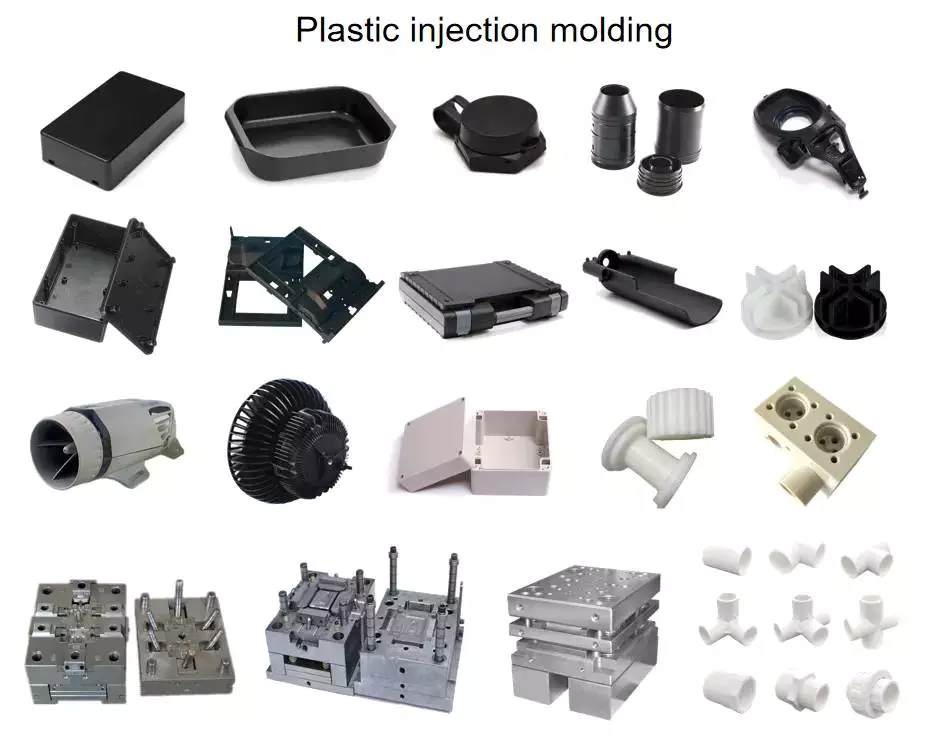
About Injection Molding
Injection molding is the most common modern method of manufacturing plastic parts. It is used to create a variety of parts with different shapes and sizes, and it is ideal for producing high volumes of the same plastic part. Injection molding is widely used for manufacturing a variety of parts, from the smallest medical device component to entire body panels of cars. A manufacturing process for producing CZPT from both thermoplastic and thermosetting materials, injection molding can create parts with complex geometries that many other processes cannot.
Other products
Production process
Company Profile
ZheJiang (HangZhou) Xihu (West Lake) Dis.xin Metal Products Co., Ltd is specialized in the production of aluminum die casting, zinc alloy die casting, and aluminum lightweight production. Since establish of 2006, we always provide the best die casting parts to customers, and now we also develop the lightweight process successfully and obtain many national patents. Our products are widely used in automobile, medical, power Industry, electrical appliance, construction, high-speed railway and so on. And we have exported to Japan, Germany, USA, Canada, Australia and many countries.
Environmental Impact Assessment & ISO 9001 Certied
Selecting a reliable and qualified partner is more different & difficult than just choosing a supplier. We have obtained the license of EIA from government and get certied of ISO 9001, and we will always process our production per as EIA & ISO requirement strictly, to guarantee the stable production, to supply the qualified parts to you and enlarge your business finally. We sincerely hope we can become your faithful partner and develop a flouring future with you.
Certifications
Packaging & Shipping
FAQ
1.Are you a manufacturer or a trading company?
We are a 3000-square-meter factory located in ZheJiang , China.
2.How can I get a quote?
Detailed drawings(PDF/STEP/IGS/DWG…) with material, quantity and surface treatment information.
3. Can I get a quote without drawings?
Sure, we appreciate to receive your samples, pictures or drafts with detailed dimensions for accurate quotation.
4.Will my drawings be divulged if you benefit?
No, we pay much attention to protect our customers’ privacy of drawings, signing NDA is also accepted if need.
5. Can you provide samples before mass production?
Sure, sample fee is needed, will be returned when mass production if possible.
6. How about the lead time?
Generally, 1-2 weeks for samples, 3-4 weeks for mass production.
7. How do you control the quality?
(1)Material inspection–Check the material surface and roughly dimension
(2) Production first inspection–To ensure the critical dimension in mass production
(3)Sampling inspection–Check the quality before sending to the warehouse
(4)Pre-shipment inspection–100% inspected by QC assistants before shipment
8. What will you do if we receive poor quality parts?
Please kindly send us the pictures, our engineers will find the solutions and remake them for you asap.
| Material: | Plastic |
|---|---|
| Application: | Medical, Household, Electronics, Automotive, Agricultural |
| Material Available: | ABS, PC, PA, PP, POM.Nylon66, etc |
| Color: | Customize Color |
| Product: | Household Product |
| Name: | Plastic Injection Molded Products |
| Samples: |
US$ 3/Piece
1 Piece(Min.Order) | |
|---|
| Customization: |
Available
| Customized Request |
|---|

Injection Molded Parts – Design Considerations
If you want to produce high-quality Injection molded parts, there are several factors to consider before the design process. These factors include the Surface finish, Material compatibility, and Tooling fabrication. This article will focus on some of these factors. Ultimately, you can save time and money by designing the parts in-house.
Design considerations
When creating a new part, or updating an existing part, design considerations for injection molded parts are critical. The decisions you make in these early stages of development can have a profound effect on the final product, and they can also have substantial cost and timing implications. In this guide, we’ll explore key design considerations, including how to maximize the efficiency of the injection molding process. We’ll also touch on how to optimize gate placement and parting lines.
To ensure a successful injection molding process, part design must balance structural integrity and plastic fill volume. This means creating parts with relatively thin walls that have adequate support and avoid warping or sinking. To do this, injection molded parts often feature ribs or projections to strengthen the walls. However, too thin of a wall can result in excessive plastic pressure and air traps.
One of the most important design considerations for injection molded parts is the direction of the parting line. For many applications, a parting line is obvious, but for others it’s a little less obvious. The first step in designing an injection mold is to determine which direction it should open.
Another critical design consideration is the part’s ejection. If a part isn’t ejected properly, it will stick to the mold. A part that has too many undercuts or ribs will end up stuck on the mold’s side, making it difficult to eject it from the mold. A part that has a draft angle of at least five degrees is much easier to eject.
Another important design consideration for an injection molded part is the type of plastic used. Some plastics do not tolerate undercuts. However, some materials are able to tolerate undercuts of up to five percent. Undercuts are not ideal and can increase the complexity and cost of the injection mold.
Another design consideration for injection molded parts is the radius of edges. Sharp corners can create high molded-in stresses and can lead to failure points. A radius eliminates this stress by redistributing the stress more evenly throughout the part. This also facilitates flow of the material through the mold.
Surface finish
Injection molded parts are often finished with additional processing in order to improve their aesthetic quality. There are a variety of finishing processes, including machining and sanding, which give injected molded parts a particular look, feel, or texture. The surface finish of a plastic part affects both its aesthetics and its functionality. According to the Society of Plastics Industry, certain standards for surface finish are essential to the aesthetics and durability of plastic parts.
Surface finish of injection molded parts depends on the primary design goal. For instance, some designs may need a part to be aesthetically pleasing while others may want to enhance its functionality. Surface texture is often used by designers and engineers to achieve different aesthetic goals, such as improving the product’s perceived value. A textured surface may also help hide imperfections and improve the part’s non-slip qualities.
Surface finish is a critical aspect of plastic injection molding. It can affect material selection, tooling, and other process decisions. It is important to determine the desired surface finish early in the design phase. A skilled plastic injection molder can assist you in making this decision. In addition to determining the finish you need, a skilled molder can help you decide the best material for the job.
The PIA classification system defines four basic grades for surface finish. There are subcategories for each grade. Group A surface finish is smooth, and grade B and C finishes are textured. The former is the most common and economical finish and is most suitable for industrial parts. It can hide deformations and tooling marks, and is the least expensive finish type.
Surface finish of injection molded parts can vary greatly, and can be crucial to the performance and appearance of the part. Some companies prefer plastic parts with a glossy finish, while others prefer a textured surface for aesthetic reasons. While the former may be better for aesthetic purposes, rougher surfaces are often preferred for functional or mechanical parts.
Material compatibility
 Material compatibility is important for the durability of your injection molded parts. You can use multiple materials in the same part by mixing resins. This is an ideal solution for parts that require adhesion, friction, or wear. Fast Radius can simplify the material selection process, optimize part design, and speed up production.
ABS is a thermoplastic polymer that can withstand a range of temperatures. Its low melting point means that it is easy to mold, and it has good chemical and moisture resistance. ABS also has good impact strength, and is highly durable. It is easy to recycle. Nylon is another versatile material for injection molding. It can be used for car tires, electrical components, and various apparel.
When choosing the material for your injection molded parts, keep in mind that the type of resin will determine their tolerance. Injection molding is compatible with a wide range of plastic resins. Some materials are more suitable than others for certain applications, and many plastics can be modified with stabilizers or additives to improve their properties. This flexibility allows the product development team to customize materials to achieve the performance characteristics they desire.
Polyamides are another great option for injection molding parts. Both natural and synthetic varieties of these plastics have excellent properties. However, they have some drawbacks. For instance, nylon injection molding is difficult and can result in inadequate filling. However, Nylon injection molding has many benefits, including high impact resistance and heat resistance.
Polybutylene terephthalate (PBT) is a high-molecular-weight polymer with excellent mechanical and chemical resistance. It is a good choice for components in the medical, automotive, and lighting industries. Its low water absorption and low flammability make it suitable for many applications.
Polyurethane (TPU) is another polymer option. It has excellent resistance to abrasion, chemicals, greases, and oils. It also has high temperature resistance, and is suitable for ozone environments. However, TPU is more expensive than TPE and requires drying before processing. Moreover, it has a short shelf life.
Tooling fabrication
 Tooling fabrication for injection-molded parts is an important component of the manufacturing process. The right design of the mold can reduce the cost and time required for a finished product. For instance, choosing the right type of core for the mold can reduce the amount of material used in the part, which is necessary to produce a high-quality product. It is also important to choose a design that is easy to mill into a mold.
Injection molding requires a mold with precise geometries. The mold tool must be constructed accurately and carefully to achieve the desired precision. It can be the biggest investment in the manufacturing process, but it is also critical to the success of a project. Large volume and high-precision parts often require more complex tooling, as they require the highest level of precision.
Tool steels typically used for injection moulding include H-13 and 420 stainless steel. Both of these materials are strong enough to produce parts of comparable hardness to wrought parts. These materials have low elongation values, so they are ideal for constructing injection moulding tools. Some of these steels also have excellent dimensional accuracy and are ideally suited for high-precision tool fabrication.
The process of plastic injection molding requires precise measuring and tooling fabrication. The mold must have the proper lead angle and space for the material to deform. Undercuts must be no larger than 5% of the diameter. Moreover, the injection molded part should be free of stripping or undercuts. Ideally, it should have a lead angle of 30o to 45o.
Various plastics can be used in the process of injection molding. The process can be used to produce cosmetic and end-use parts. Materials used in the molding process include silicone rubber and thermoplastics. If the part requires additional reinforcement, it can be reinforced with fibers, mineral particles, or flame retardant agents.
Increasingly advanced technologies have streamlined the process of tooling fabrication for injection moulded parts. The process has improved with the use of computer aided design, additive manufacturing, and CNC lathes. Approximately 15% of the cost of a finished injection molded part is spent on tooling fabrication.
editor by CX 2023-07-07
China best Custom OEM Injection Molded Plastic Rubber Machinery Parts injection molding aluminum parts
Product Description
[Custom oem injection molded plastic rubber machinery parts]
Company Information
Our company is located in HangZhou City,ZheJiang , the world’s manufacturing capital. We are dedicated to the production of CNC milling & turning parts and high-precision mold components, machined parts and all kinds of Knives & Blades according to the requirements of customers from different industries. Products are mainly exported to Europe, USA and Japan, and obtains favor reputation from customers.
We will always adhere to the values of “Details, Focusing, Principal, Leading” and the business philosophy of “Constantly Improvement, Precision Dedication” to serve the customers more and better and to create value for customers.
OUR SERVICES
We specialize in CNC Machined Parts,Precision Injection Mold Parts, Plasic Injection Moulding, and Machining all kinds of Knives and Blades.
OUR INDUSTRIES
We serve in the industries of Automobile, Mobile Phone, Computer and Medical Parts, Home Appliances, Led Lights, Electrotechnical Application, Aerospace, Consumer Electronics, Watches, Agriculture, Food Packaging & Processing and Archery, Telescope,UAV,Robot,etc.
Products Description
| Material: | PMMA,PC,PP,PEEK,PU,PA,POM,PE,UPE,etc. |
| Color: | White,black,green,nature,blue,yellow,etc. |
| Diameter: | 5-1000mm,or customized. |
| Shape: | According to your drawings. |
| Certification: | ISO9001,SGS,Test Report,RoSH. |
| Advantage | One stop procurement. |
| Packing | Plastic bags,Cartons,Wodden case,Pallet,Container,ect. |
| Mold Processing | CNC machining,Drilling, EDM,and then testing. |
| File Formats | Solid Works(STEP), Pro/Engineer, AutoCAD(DXF,DWG), PDF,etc. |
| Negotiations: | Quality,material,price,payment,delivery time item and so on |
| R&D: | According to customer’s requirements,we could design and improve the 3D moulding files. |
| We will send our customers the 3D files for confirmation.Once the customers approved,then we will start to build the mold. | |
| Sample confirm: | We can send the trial sample to customers for approval, If the customers are not satisfied it, then we will modify the mould. |
| Other | 24 hours instant and comfortable customer service. |
| Shipping status notification during delivery. | |
| Regular notification of new styles & hot selling styles. |
Logistic
| Shaping Mode: | Injection Mould |
|---|---|
| Surface Finish Process: | Polishing |
| Mould Cavity: | Multi Cavity |
| Plastic Material: | ABS |
| Application: | Car, Household Appliances, Furniture, Commodity, Electronic, Home Use |
| Design Software: | Pro-E |
| Samples: |
US$ 1/Piece
1 Piece(Min.Order) | |
|---|
| Customization: |
Available
| Customized Request |
|---|
Designing Injection Molded Parts
Injection molded parts are a great way to produce fast, reliable parts without having to spend much time on post-processing. Whether you’re designing a small component or a large vehicle, you can expect your parts to be ready to use right away. Because of their high-speed production cycles, you can expect your parts to be delivered within 30 to 90 seconds.
Design considerations for injection molded parts
 When developing a medical device, there are several design considerations to be made to create a quality injection molded part. Typically, product designers want to minimize the amount of material needed to fill the part while still maintaining the structural integrity of the product. To this end, injection molded parts often have ribs to stiffen the relatively thin walls. However, improper placement of ribs or projections can create molding problems.
Design considerations for injection molded parts include the overall shape and finish of the part. There are several ways to make the part look better. One way is to make the surface smoother and less pronounced. This will help the material flow evenly throughout the mold and minimize the risk of parting lines. Another way to reduce the risk of sink marks is to reduce the thickness of ribs relative to the nominal wall thickness of the part.
A common problem encountered when designing injection molded parts is sink marks. These can be difficult to avoid. A molder may not be willing to guarantee the product’s surface is sink-free, so designers must make sure that sink marks are minimized. To prevent these problems, the design of the parts should be as simple as possible.
Injection molded parts can also have complex geometries, and the design process is incredibly flexible. A good molder will be able to reproduce complex parts at low cost. To get the best possible results, designers should discuss the design and process with the molder. They should also discuss with the molder any critical tolerance specifications. The designer should also consider reworking the mold if necessary.
The wall thickness of a plastic injection molded part should be consistent. This is important because it influences the part’s functionality and performance. An uneven wall thickness can result in sink marks, voids, and other undesirable effects. It may also result in excessive plastic pressure or cause air traps.
Materials used in injection molded parts
When designing a product, materials used in injection molding are an important factor in the end result. These materials vary in strength, reusability, and cost. Understanding these differences is essential for ensuring the best product. In addition, understanding the characteristics of these materials can help you plan your budget and determine which ones are right for your application.
Choosing the wrong material can have serious consequences. In addition to premature component failure, the wrong choice can also increase your cost. To avoid such an occurrence, it’s a good idea to seek expert advice. Expert consultations can help you understand the factors that are important for your particular plastic molding project.
Fortron PPS: This thermoplastic resin offers excellent strength, toughness, and chemical resistance. It’s also stiff and durable, which makes it ideal for demanding industrial applications. Other common plastics include Nylon 6/6, which is strong and lightweight. Its high melting point makes it a great replacement for metal in certain environments. It also offers desirable chemical and electrical properties. PEEK is another common material used in injection molding.
ABS: Another engineering grade thermoplastic, ABS offers excellent heat resistance and chemical resistance. The disadvantage of ABS is its oil-based composition. As a result, ABS production creates noxious fumes. Nylon is another popular plastic for injection molding. Nylon is used in many different applications, from electrical applications to various kinds of apparel.
Injection moulding is a process where raw material is injected through a mold under high pressure. The mold then shapes the polymer into a desired shape. These moulds can have one or multiple cavities. This enables manufacturers to create different geometries of parts using a single mould. Most injection moulds are made from tool steel, but stainless steel and aluminium are also used for certain applications.
Characteristics of injection molded parts
 Injection molded parts exhibit a range of mechanical and physical properties. These properties affect the performance of the parts. For example, they can affect electrical conductivity. Also, the degree of filling in the parts can determine their mechanical properties. Some studies have even found that filling content can affect the dimensional accuracy of the parts.
To ensure the highest quality of the molded parts, it is important to inspect the machines and processes used to manufacture them. Proper maintenance can prevent mistakes and prolong the service life of the components. Moreover, it is essential to clean and lubricate the machine and its components. This will also reduce the possibility of mold errors.
The temperature and pressure characteristics of the injection mold can be characterized with the help of a simulation tool. For example, in a simulation environment, the injection pressure can be set as a profile and is equal to the pressure in the flow front. Moreover, the maximum injection pressure can be set as a value with minimum dependence on the flow rate. The temperature of the material used in the injection mold should be within a recommended range.
The temperature and pressure of the mold cavity must be monitored to ensure proper ejection. The temperature of the injection mold cavity is usually set at a temperature slightly above the ejection temperature. This can be manually or automatically. If the temperature is too high, the part will not be able to eject. The rapid temperature change can cause the part to warp. The same applies to the cooling time of the mold and cavity.
The thickness of the molded part should be uniform. If the injection mold does not conform to the required thickness, sink marks may be visible. A minimum of 2.5 mm between the outer and inner diameters is required for proper ejection.
Common problems encountered
There are several common problems encountered during the production of injection-molded parts. One of the most common of these is sink marks. These appear on the surface of the part and are a result of uneven cooling of the plastic within the mold. This problem can be caused by poor mold design, insufficient cooling time, and/or low injection pressure.
The first common problem occurs when the mold is not tightly clamped. This causes the molten plastic to be forced out of the mold. Other problems may occur due to the wrong clamping pressure or temperature. In these cases, the clamping force should be increased or the mold design should be revised to allow the plastic to flow properly through it. In addition, a poor quality mold may cause flash or burrs.
Another common problem is wavy patterning. These two defects can affect the appearance and functionality of the part. To avoid these problems, work with an experienced injection molding manufacturer who has experience in these types of parts. They will be able to troubleshoot and minimize any potential risks.
One of the most common problems encountered in injection molding is discoloration. A discolored part will be black or rust-colored. This problem is caused by an excess of air in the mold cavity, and can be avoided by reducing the injection speed. Ventilation systems can also be adjusted to minimize the chances of these problems.
Defective molds can cause a negative impact on the bottom line. By understanding the common problems encountered during injection molding, you can better avoid these problems and make your products as attractive as possible.
Fasteners used in injection molded parts
 Injection molded parts often use fasteners for securing fastener elements in place. As shown in FIGS. 7 and 8 (two separate views), the fastener elements are integrated with the molded product, and they extend from one side. The fastener elements are designed to engage loop elements in the overlying layer. The palm-tree shaped fasteners are especially well-suited for this purpose, as their three-dimensional sides engage more loops than flat sides. These features result in a more secure closure.
When fasteners are used in injection molded parts, the plastic is injected into a mold, with the fastener integrated. In addition to self-tapping screws, other plastic fasteners can include moulded or pre-drilled pilot holes. This method avoids the need for a secondary assembly step and ensures an easy fit. These screws also have other advantages, including a smaller thread profile and lower radial stress, which prevents boss damage.
Another type of fastener commonly used in injection molded parts is a boss. This type of fastener is typically larger than the nut and the pilot hole. An undersized boss can lead to warpage during the injection molding process and cause a product to fail in the field.
Another type of fastener used in injection molded parts is a thread insert, which is usually a stainless steel A2 wire. There are different versions of this fastener for different materials, including carbon fiber reinforced plastic. And the fastener can be modified to adjust the size of the hole.
These fasteners are used in many different types of injection molded parts. Some parts are used to fix a variety of cosmetic issues, such as minor sinks. While these are not defects, they may not look perfect, and they can affect the overall appearance of a product. If you want to improve the appearance of an injection molded part, you can add fibers and glass fibers, as well as colorants.
editor by CX
2023-04-14
China Plastic Injection Mould Manufacture Customized Machinery Parts Plastic Injection Mold Over Moulding Parts with high quality
Product Description
Product Description
Plastic injection CZPT manufacture customized Machinery parts plastic injection mold Over moulding parts.
Below is an example of Over molded parts to show the over molding parts.
Over-molded: means during injection, the metal insert should be injected to the plastic parts.
Product Parameters
NOTE: BELOW INFORMATION IS JUST OUR STHangZhouRD SPECIFICATION. AND WE USUALLY DO CUSTOMIZATION ACCORDING TO YOUR REQUIREMENT. SO FOR YOUR PROJECT, PLEASE SEND:
*** 3D drawing in stp, step format, our engineer will check the 3D drawing to see if the mold can be realized or not.
*** Material should be advised. Usually, the film PET(0.125,0.188 thickness), and plastic is usually PC or ABS+PC
*** 2D file to show the tolerance and surface requirement, we can reach toleracnce for mold +-0.05mm. We will check if the parts can be injected
or should use IML/IMD technology (we have anti-dust workshop for IML/IMD printing, Fixing and IML/IMD injection)
*** Advice the materials for the products: different parts needs different material according to application.
*** Your plan for total qty for this part, so that we can decide to make cavity numbers according to qty.
*** Surface requirement for parts should be advised so that we can know how to make the mold surface to realize the part surface. Generally
has many kinds of surface such as: Polishing, Sand blasting, Matt, Texture, Anodization…
OUR ADVANTAGE: WE WILL BOTH CONSIDER TO SAVE MOLD COST AND PRODUCT COST, SO YOUR INFORMATION IS VERY IMPORTANT FOR US. WE ARE VERY PROFESSIONAL IN IMD/IML INJECTION, OVER MOLDED INJECTION
| Parts material | PP, ABS, PC, PC+ABS, PE, LDPE, PA66, POM, PMMA… customized material according to part application or use |
| Mold Cavity | We decide the cavity according to customer’s total qty planing and part construction. For example, if the part can be made in multi cavity, also the selling plan qty is quite big, then we will adapt multi cavity; even if the qty is big, but if the part size is quite big, we also can only make single cavity… so should be discussed. |
| Gate | Subgate, Pin gate… according to product design |
| Shot time | 10-120seconds according to product design, mold design |
| Runner | Cold or hot runner, it depends on the material, cavity, part construction… so should be discussed |
| Mold life | At least 300000 shots.Maximum can be 1,200,000 shots if with good maintence. |
| Injection Machine | According to the part size and qty of cavity, we have machines from 60tons to 800 tons… |
| Mold delivery time | 25-50 days including mold testing running around 2-3 times. |
Detailed Photos
Below we just show some parts pictures which we have made for some customers. We have made many automotive parts, medical parts, mechanical parts, electronic parts, home appliance parts, industry parts.
Certifications
Our factory has been certified by ISO association adn NAQ16949 for Auto parts
Company Profile
Cents is a factory with 20 years of experience in mold making and injection molding. Currently, the company and its factory covers an area of 13,000 square meters and has around 200 workers. Among them, 26 are design engineers and structural engineers. We have a complete mold production workshop, injection workshop, dust-free injection workshop, inspection room, warehouse, and assembly workshop. We have advanced EDM and WEDM mold production equipment imported from Japan. We have 46 injection molding machines, 19 of which are Japanese Sodick brand, in order to produce high-precision plastic products. Our products are widely used in the new energy automobile industry, medical industry, mechanical and machinery industry, home appliance industry and beauty industry. Among them, we are very professional and have rich experience in the production of negative pressure cups, tapping thread products and transparent acrylic products.
In 2019, we started to carry out the IMD/IML process and established an IMD/IML product production workshop, specifically for some customers who have very high requirements for product appearance and process.
Our factory has always adopted ISO 9001 as its operating principle. In terms of auto parts products, we have been certified by the 16949 organization and issued a 16949 certificate.
Our company only focuses on ODM/OEM design and production. Therefore, to provide customers with the best quality design, production and service is our company’s core value requirements;
Our Advantages
***More than 40 sets injection machines;
***More than 20 engineers and 200 workers;
***One-stop service in making mold and molding;
***Anti-dust workshop for IMD/IML molded parts;
***Assembly line available for some finished parts;
***Most advanced equipment for EDM & WEDM, Sodick brand injection machine
Our Main Products
Customer Comments
|
US $0.8-2.5 / Piece | |
1 Piece (Min. Order) |
###
| Plastic Type: | Thermosoftening Plastic |
|---|---|
| Plastic Form: | Liquid |
| Molding Method: | Injection Molding |
| Transport Package: | Packed in Cartons |
| Trademark: | Cents or Customized |
| Origin: | Made in China |
###
| Samples: |
US$ 300/Piece
1 Piece(Min.Order) |
|---|
###
| Customization: |
Available
|
|---|
###
| Parts material | PP, ABS, PC, PC+ABS, PE, LDPE, PA66, POM, PMMA… customized material according to part application or use |
| Mold Cavity | We decide the cavity according to customer’s total qty planing and part construction. For example, if the part can be made in multi cavity, also the selling plan qty is quite big, then we will adapt multi cavity; even if the qty is big, but if the part size is quite big, we also can only make single cavity… so should be discussed. |
| Gate | Subgate, Pin gate… according to product design |
| Shot time | 10-120seconds according to product design, mold design |
| Runner | Cold or hot runner, it depends on the material, cavity, part construction… so should be discussed |
| Mold life | At least 300000 shots.Maximum can be 1,200,000 shots if with good maintence. |
| Injection Machine | According to the part size and qty of cavity, we have machines from 60tons to 800 tons… |
| Mold delivery time | 25-50 days including mold testing running around 2-3 times. |
|
US $0.8-2.5 / Piece | |
1 Piece (Min. Order) |
###
| Plastic Type: | Thermosoftening Plastic |
|---|---|
| Plastic Form: | Liquid |
| Molding Method: | Injection Molding |
| Transport Package: | Packed in Cartons |
| Trademark: | Cents or Customized |
| Origin: | Made in China |
###
| Samples: |
US$ 300/Piece
1 Piece(Min.Order) |
|---|
###
| Customization: |
Available
|
|---|
###
| Parts material | PP, ABS, PC, PC+ABS, PE, LDPE, PA66, POM, PMMA… customized material according to part application or use |
| Mold Cavity | We decide the cavity according to customer’s total qty planing and part construction. For example, if the part can be made in multi cavity, also the selling plan qty is quite big, then we will adapt multi cavity; even if the qty is big, but if the part size is quite big, we also can only make single cavity… so should be discussed. |
| Gate | Subgate, Pin gate… according to product design |
| Shot time | 10-120seconds according to product design, mold design |
| Runner | Cold or hot runner, it depends on the material, cavity, part construction… so should be discussed |
| Mold life | At least 300000 shots.Maximum can be 1,200,000 shots if with good maintence. |
| Injection Machine | According to the part size and qty of cavity, we have machines from 60tons to 800 tons… |
| Mold delivery time | 25-50 days including mold testing running around 2-3 times. |
Design Considerations for Injection Molded Parts
There are many factors to consider when designing a component for injection molding. These include design factors, materials, overhangs, and process. Understanding these factors will make it easier to choose the right part for the application. In this article, we’ll go over several of the most common design considerations.
Design factors
 To get the best results from your injection molded parts, you must ensure that they meet certain design factors. These factors can help you achieve consistent parts and reduce cost. These guidelines can also help you to avoid common defects. One of the most common defects is warping, which is caused by the unintended warping of the part as it cools.
When designing injection molded parts, the draft angle is critical. Increasing the draft angle allows the part to emerge cleanly from the mold and reduces stress concentration. This can improve the part’s function and speed up the production process. In addition, it ensures a uniform surface finish. Incorrect draft angles can result in parts that are not functional and can cost you money. If your product team doesn’t pay attention to these design factors, they could end up destroying expensive molds and producing a high number of rejects.
Ribs are another design factor that should be taken into consideration. Rib height should be less than three times the thickness of the part’s wall. This will prevent sink marks and minimize the chances of the ribs sticking inside the mold.
Materials
There are many options when it comes to materials for injection molded parts. Choosing the right material will affect how well it performs in your particular application. If you need a large part to be flexible and sturdy, then a plastic with good flow properties will work best. Injection molded plastics come in a variety of different resins. Choose the one that best meets your application’s needs, considering its main functionality and the desired appearance. You may also want to choose a material that is UV resistant, heat resistant, flexible, and food safe.
Polymers that are suitable for injection molding include polycarbonate and polypropylene. These materials are flexible and strong, and can be used to create parts with high-level details. These materials are also lightweight and inexpensive. Despite being flexible, they are not suitable for high-stress applications.
During the molding process, the injected material must be cooled, otherwise it will expand again. This is why you need to keep the temperature of the mould at 80 degrees Celsius or less.
Process
Injection molding is the process of creating plastic parts. The plastic is melted in a mold and then forced to cool. It then solidifies into the desired shape. During the cooling process, the plastic can shrink, so it is important to pack the material tightly in the mold to prevent visible shrinkage. When the mold is completed, it cannot be opened until the required cooling time has passed. This time can be estimated based on the thermodynamic properties of plastic and the maximum wall thickness of the part.
The mold must be precisely designed and tested. The process can be repeated many times, which makes it ideal for mass production. It is also one of the fastest ways to scale production. The more parts a mold can produce, the lower its cost per piece. This is one of the benefits of injection molding.
Injection molding parts are used for many industries, including appliances, electronics, packaging, and medical devices. They can be made to have complicated shapes.
Overhangs
 Overhangs are areas of extra material that surround the surface of an injection molded part. This extra material is typically made of inexpensive material that is edged or glued on the part’s surface. The overhang material can be easily separated from the blank using a simple cutting process.
The amount of material needed for an overhang is dependent on the shape of the part and the amount of surface area. Generally, an overhang is less than 15 percent of the cost of the part. Usually, the material used should be able to fulfill the overhang’s function and differentiate it from the material in the form flachen area.
Overhangs on injection molded parts should be avoided because they may cause the design to become unstable. To avoid this problem, consider designing your part so that the sides and edges are parallel to one another. This will help ensure that the part will be free of undercuts and overhangs.
Overhangs on injection molded parts can be avoided by ensuring that the parts are designed with tolerances in mind. For example, an overhang in an injection molded part can cause a mold to have an overhang that is too small for the machine. This can cause problems in the manufacturing process, and it can result in a costly mold.
Cost
Injection molding costs can vary depending on the complexity of the part, the size and the type of plastic. Parts with complex geometries may require additional design work and tooling. Larger parts can also cost more than small ones. The amount of time spent designing and producing them is also important.
To reduce the cost of injection molding, a manufacturer must consider two major factors: tooling and the material used. The plastic used for injection molding has several different properties, which will impact the part price. For instance, plastics with a lot of glass fibers will reduce the amount of time necessary to repair the mold. Another factor to consider is the thermal properties of the material.
The next major factor in the cost of injection molded parts is the material of the injection mold. While most of these molds are made of steel, the type and grade of steel used is important. Injection molds are also required to have nearly wear-free interior cavities. This is necessary to maintain tight tolerances.
Another factor that contributes to the cost of injection molded parts is the cost of bulk material. This material costs money and requires expensive electricity to process. Typically, the more parts you produce, the lower the cost per pound. Storage of bulk material is also a significant expense. Therefore, a quicker cycle time will reduce storage costs.
Reliability
While manufacturing involves some degree of variation, the variation should be within acceptable limits. This is essential if you want to produce high-quality, dimensionally stable parts. A reliable manufacturing process involves precise control over mold tooling and part design. It also requires repeatability in both quality and production processes.
A reliable injection molding process also focuses on detecting defects early in the production process. Invisible hazards, such as air pockets, mold materials compromised by overheating, and more, can lead to failure. These defects will most likely not be discovered by simple visual inspection and may not come to light until after warranty claims are filed from the field. By finding the defects in the early stages, manufacturers can maximize productivity and reduce costs by minimizing the number of replacement parts needed.
The process of building a custom mould for plastic components is highly skilled. A perfect mould will eliminate potential defects and ensure that the production process is reliable. Traditionally, this process relied on trial and error, which added time and money to the production process.
Design for manufacturability
 When designing injection molded parts, it is imperative to keep in mind their manufacturability. Injection molding allows for complex geometries and multiple functions to be combined into a single part. For example, a hinged part can have a single mold that can produce two different halves. This also decreases the overall volume of the part.
Injection molded parts do not typically undergo post-processing. However, the mold itself can be finished to various degrees. If the mold is rough, it can cause friction during the ejection process and require a larger draft angle. Detailed finishing procedures are outlined by the Society of Plastics Industry.
The process of designing injection molds is very exacting. Any errors in the mold design can lead to out-of-spec parts and costly repair. Therefore, the process of Design for Manufacturability (DFM) validation is a key step early in the injection molding process. Fictiv’s DFM feedback process can identify design challenges and provide early feedback to minimize lead times and improve quality.
The surface of an injection molded part can develop sink marks, which occur when the material has not fully solidified when it is ejected from the mold. Parts with thick walls or ribs are more prone to sinking. Another common defect in plastic injection molding is drag marks, which occur when walls scrape against one another during ejection. In addition to sink marks, parts with holes or exposed edges can form knit lines.
editor by czh 2022-12-07
China Small Batches Production CNC Machining Parts Precision CNC Turning Machining Service Aluminum Machinery Parts with Anodizing injection molded plastic auto parts
Product Description
Small batches production cnc machining parts precision cnc turning machining service aluminum machinery parts with anodizing
| Factory: | Rollyu Precision Machining Co., Ltd |
| Production Description | Customized Aluminum/Steel/Plastic CNC Turning/ Machining / Milling Parts for Non-Standard Devices/Medical Industry/Electronics/Auto Accessory/Vision Lighting |
| Processing | Machining, Turning, Milling, Grinding, Wire-EDM,Fabrication service etc. |
| Material for CNC Machining processing | 1) Aluminum – AL 6061-T6, 6063, 7075-T,5083,6063,6082,5052,2A12 etc. |
| 2) Stainless steel – SS 201,SS301 SS303,SS304,SS316L, SS416L,17-4(SUS630),440C, 430 etc. | |
| 3) Steel – 4140,4340,Q235, Q345B,20#,Cr12MoV,D2,A2,4140,4150,P20,S136,M2,O2, SKD11,CRS, etc. | |
| 4) Titanium – TA1,TA2/GR2, TA4/GR5, TC4, TC18 etc. | |
| 5) Brass – C36000 (HPb62), C37700 (HPb59), C26800 (H68), C22000(H90) etc. | |
| 6) Copper – bronze,Phosphor Bronze, Magnesium alloy, etc. | |
| 7) Plastic – Peek, Nylon, G-10, Acrylic,Anti-Static Acetal Tan (Tecaform SD) , PC,ABS, etc. | |
| 8) Food class ,Medical class- such as POM, Delrin, etc. | |
| 9) Aerospace class – PEI+30%GF,PEEK+30%GF,PC+30%GF,PU,PTFE,PE,PVC etc. | |
| 10) Rollyu Precision handles many other type of materials, please kindly contact us if your required material is not listed above. | |
| Finish | For Aluminum parts – Clear anodized, Color anodized, Hard anodized, Sandblasting, Chemical film, Brushing, Polishing, Painting, Silk screen printing,Etching, Laser marking, etc. |
| For Stainless steel parts – Polishing, Passivation,PVD, Sandblasting, Black oxide, Electrophoresis black, Painting, Silk screen printing,Etching, Laser marking, etc. | |
| For Steel parts – Polishing, Black oxide, Nickel /Zinc/Gold/ Chrome/Silver plating, Carburized, Powder coating,electrophoresis, QPQ(Quench-Polish-Quench), Heat treatment, Painting, Silk screen printing,Etching, Laser marking, etc. etc. |
|
| For Brass parts – Nickel /Zinc/Gold/ Chrome/Silver/Titanium plating, Electrophoresis black, Powder coating,Painting, Silk screen printing,Etching, Laser marking, etc. | |
| For Plastic parts – Plating (ABS), Brushing (Acylic),Painting, Silk screen printing,Etching, Laser marking, etc. | |
| Rollyu Precision handles many other type of finish, please kindly contact us if your required finish is not listed above. | |
| Tolerance | Minumum tolerance +/- 0.05mm (+/- 0.0005″) |
| Surface roughness | Ra 0.1~3.2 |
| Drawing format | Step/Igs/PDF/DWG/DXF, etc. |
| Testing equipment | CMM (Coordinate Measuring Machine),Height gauge, Caliper, Hardness tester, Roughness tester, Projector machine, Pin/Angle/Block/Plug/Thickness/Thread/Radius gauge,etc. |
| MOQ | 1 piece |
| Lead time | 2 weeks after received order. |
| Certificate | ISO9001, ISO13485. |
| Inspection processing | IQC,IPQC, FQC, QA. |
| Capacity | CNC turning work range: φ0.5mm-φ650mm*600mm. |
| CNC milling work range: 880mm*1300mm*600mm. | |
| Application | Automation, Medical device, Consumer Electronics, Security, IoT, Energy, etc. |
Rollyu Precision Machining Co., Ltd located in HangZhou, China, is a mechanical manufacturer providing a wide range of custom specialty plastic injection molded parts, cnc machining parts, Sheet Metal Fabrication, Liquid Silicone Rubber Injection Parts, Aluminum Extrusion, Sub-assemblies ,along with advanced over molding capability.
Serving markets including Security systems, Fire systems, Marine ,Health care, Medical Devices, Personal Care, Networking, Internet of Things (IoT), Xihu (West Lake) Dis.n Machine Interaction (HMI) , Consumer Electronics, Telecommunications and Renewable Energy as well as many others with solutions for a variety of challenges they face in these high paced, ever-changing industries. Rollyu Precision provides mechanical components and sub-assemblies to many of the top companies worldwide.
With many years of mechanical parts manufacturing, we continue to expand our capabilities and are well positioned to offer concept-to-commercialization solutions. Rollyu Precision can provide over molding capabilities to streamline timelines and costs. If medical device engineering and design for manufacturing services are needed, our project teams are aligned to provide those services, including tool and fixture fabrication and rapid prototyping.
Examples Of Services And Capabilities Include:
- Engineering DFM Services
- CNC Swiss Machining, Milling, and Turning
- Over molding and Injection Molding
- Plastic Injection Molded Parts
- Liquid Silicone Rubber Injection Parts
- Aluminum Extrusion
- Sheet Metal Fabrication
- Sub-assemblies
For a more complete list, please send us inquiry.
Rollyu Precision has unrivalled links with the companies Medical device, Instrumentation, Security systems, IoT, HMI, Automation, Photonics, Energy, Marine and many others industries. We have mutually beneficial relationships with nearly 150 companies around the world, from the smallest company to the largest enterprise.
For our partners, we deliver world-class machining parts, plastic molded parts , silicone rubber parts, sheet metal fabrication, heat sink, and assembly components. We can manufacture from single parts to sub-assemblies to meet challenges and your goals.
Quick Response After-sales Service
Rollyu Precision after sales service is based on our detailed knowledge of our team, our machines and our accumulated experiences, thus enabling our technicians to rapidly identify and resolve any potential problems.
A periodic diagnosis minimizes the risk of unexpected events and increases productivity. Moreover, all basic components are checked 100% before shipment.
We look forward to your RFQ or a trial order firstly.
Thank you for your time for having a visist at our on-line shop.
Sincerely
Tina/Rollyu Precision
FAQ
Q1: Are you a trading company or a factory ?
A1: We are a manufacturer specialized in precision parts OEM, Machining parts, Plastic injection molding, Plastic parts, Silicone and rubber parts, Heat sink, sheet metal fabrication as well as Sub-assembly.
Q2: Do you accept to manufacture the customized products based on our design?
A2: Yes, we are a professional factory with an experienced engineering team, would like to provide the OEM service.
Q3: How can I get the quotation?
A3: We will offer you the quotation within 24 working hours after receiving your detailed information. In order to quote you faster and more accurate, please provide us the following information together with your inquiry:
1) CAD or 3D Drawings
2) Tolerance.
3) Material requirement
4) Surface treatment
5) Quantity (per order/per month/annual)
6) Any special demands or requirements, such as packing, labels, delivery,etc.
Q4: Will my drawings be safe after sending to you?
A4: Sure, we will keep them well and not release to others without your permission.
Q5: How long is the lead-time for a mold and plastic parts, machining parts, sheet metal fabrication?
A5: It all depends on the mold (parts) size and complexity.
Normally, the lead time is 18-20 days for molds, 15-20 days for plastic parts. If the molds are very simple and not big, we can work out within 15 days.
The lead time for machining parts is around 2-4 weeks.
For sheet metal fabrication the lead time is around 3-5 weeks.
Q6: I have no 3D drawing, how should I start the new project?
A6: You can supply us the sample or provide us the product sizes and let us know the detailed requirements, our engineers will help you to work out the 3D drawing.
Q7: If you make poor quality goods, will you refund our fund?
A7: As a matter of fact, we won’t take a chance to do poor quality products. Meanwhile, we manufacture good-quality products until your satisfaction.
Q8: Is it possible to know how are my products going on without visiting your factory?
A8: We will offer a detailed production schedule and send weekly reports with digital pictures and videos which show the machining progress.
| To Be Negotiated | 1 Piece (Min. Order) |
###
| Application: | Fastener, Auto and Motorcycle Accessory, Hardware Tool, Machinery Accessory, Printing Machine |
|---|---|
| Standard: | GB, EN, API650, China GB Code, JIS Code, TEMA, ASME |
| Surface Treatment: | Anodizing |
| Production Type: | Batch Production |
| Machining Method: | CNC Machining |
| Material: | Nylon, Steel, Plastic, Brass, Alloy, Copper, Aluminum, Iron, Stainless Steel |
###
| Samples: |
US$ 1/Piece
1 Piece(Min.Order) |
|---|
###
| Customization: |
Available
|
|---|
###
| Factory: | Rollyu Precision Machining Co., Ltd |
| Production Description | Customized Aluminum/Steel/Plastic CNC Turning/ Machining / Milling Parts for Non-Standard Devices/Medical Industry/Electronics/Auto Accessory/Vision Lighting |
| Processing | Machining, Turning, Milling, Grinding, Wire-EDM,Fabrication service etc. |
| Material for CNC Machining processing | 1) Aluminum – AL 6061-T6, 6063, 7075-T,5083,6063,6082,5052,2A12 etc. |
| 2) Stainless steel – SS 201,SS301 SS303,SS304,SS316L, SS416L,17-4(SUS630),440C, 430 etc. | |
| 3) Steel – 4140,4340,Q235, Q345B,20#,Cr12MoV,D2,A2,4140,4150,P20,S136,M2,O2, SKD11,CRS, etc. | |
| 4) Titanium – TA1,TA2/GR2, TA4/GR5, TC4, TC18 etc. | |
| 5) Brass – C36000 (HPb62), C37700 (HPb59), C26800 (H68), C22000(H90) etc. | |
| 6) Copper – bronze,Phosphor Bronze, Magnesium alloy, etc. | |
| 7) Plastic – Peek, Nylon, G-10, Acrylic,Anti-Static Acetal Tan (Tecaform SD) , PC,ABS, etc. | |
| 8) Food class ,Medical class- such as POM, Delrin, etc. | |
| 9) Aerospace class – PEI+30%GF,PEEK+30%GF,PC+30%GF,PU,PTFE,PE,PVC etc. | |
| 10) Rollyu Precision handles many other type of materials, please kindly contact us if your required material is not listed above. | |
| Finish | For Aluminum parts – Clear anodized, Color anodized, Hard anodized, Sandblasting, Chemical film, Brushing, Polishing, Painting, Silk screen printing,Etching, Laser marking, etc. |
| For Stainless steel parts – Polishing, Passivation,PVD, Sandblasting, Black oxide, Electrophoresis black, Painting, Silk screen printing,Etching, Laser marking, etc. | |
| For Steel parts – Polishing, Black oxide, Nickel /Zinc/Gold/ Chrome/Silver plating, Carburized, Powder coating,electrophoresis, QPQ(Quench-Polish-Quench), Heat treatment, Painting, Silk screen printing,Etching, Laser marking, etc. etc. |
|
| For Brass parts – Nickel /Zinc/Gold/ Chrome/Silver/Titanium plating, Electrophoresis black, Powder coating,Painting, Silk screen printing,Etching, Laser marking, etc. | |
| For Plastic parts – Plating (ABS), Brushing (Acylic),Painting, Silk screen printing,Etching, Laser marking, etc. | |
| Rollyu Precision handles many other type of finish, please kindly contact us if your required finish is not listed above. | |
| Tolerance | Minumum tolerance +/- 0.05mm (+/- 0.0005") |
| Surface roughness | Ra 0.1~3.2 |
| Drawing format | Step/Igs/PDF/DWG/DXF, etc. |
| Testing equipment | CMM (Coordinate Measuring Machine),Height gauge, Caliper, Hardness tester, Roughness tester, Projector machine, Pin/Angle/Block/Plug/Thickness/Thread/Radius gauge,etc. |
| MOQ | 1 piece |
| Lead time | 2 weeks after received order. |
| Certificate | ISO9001, ISO13485. |
| Inspection processing | IQC,IPQC, FQC, QA. |
| Capacity | CNC turning work range: φ0.5mm-φ650mm*600mm. |
| CNC milling work range: 880mm*1300mm*600mm. | |
| Application | Automation, Medical device, Consumer Electronics, Security, IoT, Energy, etc. |
Designing Injection Molded Parts
Injection molded parts are a great way to produce fast, reliable parts without having to spend much time on post-processing. Whether you’re designing a small component or a large vehicle, you can expect your parts to be ready to use right away. Because of their high-speed production cycles, you can expect your parts to be delivered within 30 to 90 seconds.
Design considerations for injection molded parts
When developing a medical device, there are several design considerations to be made to create a quality injection molded part. Typically, product designers want to minimize the amount of material needed to fill the part while still maintaining the structural integrity of the product. To this end, injection molded parts often have ribs to stiffen the relatively thin walls. However, improper placement of ribs or projections can create molding problems.
Design considerations for injection molded parts include the overall shape and finish of the part. There are several ways to make the part look better. One way is to make the surface smoother and less pronounced. This will help the material flow evenly throughout the mold and minimize the risk of parting lines. Another way to reduce the risk of sink marks is to reduce the thickness of ribs relative to the nominal wall thickness of the part.
A common problem encountered when designing injection molded parts is sink marks. These can be difficult to avoid. A molder may not be willing to guarantee the product’s surface is sink-free, so designers must make sure that sink marks are minimized. To prevent these problems, the design of the parts should be as simple as possible.
Injection molded parts can also have complex geometries, and the design process is incredibly flexible. A good molder will be able to reproduce complex parts at low cost. To get the best possible results, designers should discuss the design and process with the molder. They should also discuss with the molder any critical tolerance specifications. The designer should also consider reworking the mold if necessary.
The wall thickness of a plastic injection molded part should be consistent. This is important because it influences the part’s functionality and performance. An uneven wall thickness can result in sink marks, voids, and other undesirable effects. It may also result in excessive plastic pressure or cause air traps.
Materials used in injection molded parts
When designing a product, materials used in injection molding are an important factor in the end result. These materials vary in strength, reusability, and cost. Understanding these differences is essential for ensuring the best product. In addition, understanding the characteristics of these materials can help you plan your budget and determine which ones are right for your application.
Choosing the wrong material can have serious consequences. In addition to premature component failure, the wrong choice can also increase your cost. To avoid such an occurrence, it’s a good idea to seek expert advice. Expert consultations can help you understand the factors that are important for your particular plastic molding project.
Fortron PPS: This thermoplastic resin offers excellent strength, toughness, and chemical resistance. It’s also stiff and durable, which makes it ideal for demanding industrial applications. Other common plastics include Nylon 6/6, which is strong and lightweight. Its high melting point makes it a great replacement for metal in certain environments. It also offers desirable chemical and electrical properties. PEEK is another common material used in injection molding.
ABS: Another engineering grade thermoplastic, ABS offers excellent heat resistance and chemical resistance. The disadvantage of ABS is its oil-based composition. As a result, ABS production creates noxious fumes. Nylon is another popular plastic for injection molding. Nylon is used in many different applications, from electrical applications to various kinds of apparel.
Injection moulding is a process where raw material is injected through a mold under high pressure. The mold then shapes the polymer into a desired shape. These moulds can have one or multiple cavities. This enables manufacturers to create different geometries of parts using a single mould. Most injection moulds are made from tool steel, but stainless steel and aluminium are also used for certain applications.
Characteristics of injection molded parts
Injection molded parts exhibit a range of mechanical and physical properties. These properties affect the performance of the parts. For example, they can affect electrical conductivity. Also, the degree of filling in the parts can determine their mechanical properties. Some studies have even found that filling content can affect the dimensional accuracy of the parts.
To ensure the highest quality of the molded parts, it is important to inspect the machines and processes used to manufacture them. Proper maintenance can prevent mistakes and prolong the service life of the components. Moreover, it is essential to clean and lubricate the machine and its components. This will also reduce the possibility of mold errors.
The temperature and pressure characteristics of the injection mold can be characterized with the help of a simulation tool. For example, in a simulation environment, the injection pressure can be set as a profile and is equal to the pressure in the flow front. Moreover, the maximum injection pressure can be set as a value with minimum dependence on the flow rate. The temperature of the material used in the injection mold should be within a recommended range.
The temperature and pressure of the mold cavity must be monitored to ensure proper ejection. The temperature of the injection mold cavity is usually set at a temperature slightly above the ejection temperature. This can be manually or automatically. If the temperature is too high, the part will not be able to eject. The rapid temperature change can cause the part to warp. The same applies to the cooling time of the mold and cavity.
The thickness of the molded part should be uniform. If the injection mold does not conform to the required thickness, sink marks may be visible. A minimum of 2.5 mm between the outer and inner diameters is required for proper ejection.
Common problems encountered
There are several common problems encountered during the production of injection-molded parts. One of the most common of these is sink marks. These appear on the surface of the part and are a result of uneven cooling of the plastic within the mold. This problem can be caused by poor mold design, insufficient cooling time, and/or low injection pressure.
The first common problem occurs when the mold is not tightly clamped. This causes the molten plastic to be forced out of the mold. Other problems may occur due to the wrong clamping pressure or temperature. In these cases, the clamping force should be increased or the mold design should be revised to allow the plastic to flow properly through it. In addition, a poor quality mold may cause flash or burrs.
Another common problem is wavy patterning. These two defects can affect the appearance and functionality of the part. To avoid these problems, work with an experienced injection molding manufacturer who has experience in these types of parts. They will be able to troubleshoot and minimize any potential risks.
One of the most common problems encountered in injection molding is discoloration. A discolored part will be black or rust-colored. This problem is caused by an excess of air in the mold cavity, and can be avoided by reducing the injection speed. Ventilation systems can also be adjusted to minimize the chances of these problems.
Defective molds can cause a negative impact on the bottom line. By understanding the common problems encountered during injection molding, you can better avoid these problems and make your products as attractive as possible.
Fasteners used in injection molded parts
Injection molded parts often use fasteners for securing fastener elements in place. As shown in FIGS. 7 and 8 (two separate views), the fastener elements are integrated with the molded product, and they extend from one side. The fastener elements are designed to engage loop elements in the overlying layer. The palm-tree shaped fasteners are especially well-suited for this purpose, as their three-dimensional sides engage more loops than flat sides. These features result in a more secure closure.
When fasteners are used in injection molded parts, the plastic is injected into a mold, with the fastener integrated. In addition to self-tapping screws, other plastic fasteners can include moulded or pre-drilled pilot holes. This method avoids the need for a secondary assembly step and ensures an easy fit. These screws also have other advantages, including a smaller thread profile and lower radial stress, which prevents boss damage.
Another type of fastener commonly used in injection molded parts is a boss. This type of fastener is typically larger than the nut and the pilot hole. An undersized boss can lead to warpage during the injection molding process and cause a product to fail in the field.
Another type of fastener used in injection molded parts is a thread insert, which is usually a stainless steel A2 wire. There are different versions of this fastener for different materials, including carbon fiber reinforced plastic. And the fastener can be modified to adjust the size of the hole.
These fasteners are used in many different types of injection molded parts. Some parts are used to fix a variety of cosmetic issues, such as minor sinks. While these are not defects, they may not look perfect, and they can affect the overall appearance of a product. If you want to improve the appearance of an injection molded part, you can add fibers and glass fibers, as well as colorants.
editor by czh 2022-11-27
China Standard custom metal parts Carbon steel agriculture machinery OEM parts silica sol precision casting agricultural spare parts suppliers
Product Number: Custom made, OEM
Solution name: Personalized Steel Components
Procedure: Expense Casting+machining
Materials: Metal
surface treatment method: Ra .8
Excess weight range: .02 to 30kg
Good quality Manage: ISO9001:2015
Finish: According to customer’s ask for
Packaging Information: 1.Distinct measurements of cartons as for each different sizes of elements 2.Pallet for air cargo 3.Plywood box for CZPT cargo
Port: HangZhou
Manufacturing Ability
| Process | Investment Casting /Lost Wax Casting / Silica sol method Casting |
| Weight | 5g-50kg |
| Capability | 150 ton per month |
| Machining Tolerance | +-.01-.03mm |
| Cast Materials | Stainless metal (316L, 316, 304, CF8, 17-4, 301, 302, 303, 310,2205, R series agri gear reducer gearmotor reducing equipment gear box speed large rpm gearbox CF8M)Carbon metal(1045, 1571, 1571, SCW450, SCW480, WCB,SCW480,WCB, 42CrMO4, 30CrNiMO)Alloy Steel |
| Surface Roughness | 6.4 Ra um /254 Ra uinches |
| other OEM Service | CNC Machining / Floor remedy (mirror polish /brush polish /powder spraying / paint spraying /chrome plating / zinc plating/impress / nickle plating ) |
| Castings Typical Application | Industrial elements: Pipe fittings / Boiler Fiting / valve component/ Railyway industries / Aerospace Industries |
| hardware / instruments ( Architectural Hardware / maritime Components / compressor /electrical electrical power tools) | |
| Machinery components ( Agricultural machinery , mining equipment, Cordless Pressure Washing Machine Agricultural Spray Pump Sprayer agriculture drone parts Pharma& food machinery and so forth ) | |
| Medical Products /Automotive Industries/harness fittings /Bridge components /Basic Enginnering | |
| Air conditioning &Refrigeration |
| Machining & Assembly | * Turning * Milling * Drilling * Uninteresting * EDM * Essential reducing * Welding * Slicing & forming * And More |
| Heat Treatment options | * Hardening * Normalizing * Quenching & ZheJiang manufacture speed reducer gear box tempering * Annealing |
| Coating | *Mirror polish *Brush polish *Powder spraying *Paint spraying *Chrome plating *Zinc plating/provoke *Nickle plating |
Types of Ball Bearings
In their most basic form, Ball Bearings have one common feature – they are made of steel. The majority of these bearings are made of 52100 steel, which has one percent chromium and one percent carbon. The steel can be hardened by heat trea
tment. 440C stainless steel is used for rusting problems. A cage around the ball balls is traditionally made from thin steel. However, some bearings use molded plastic cages to save money and friction.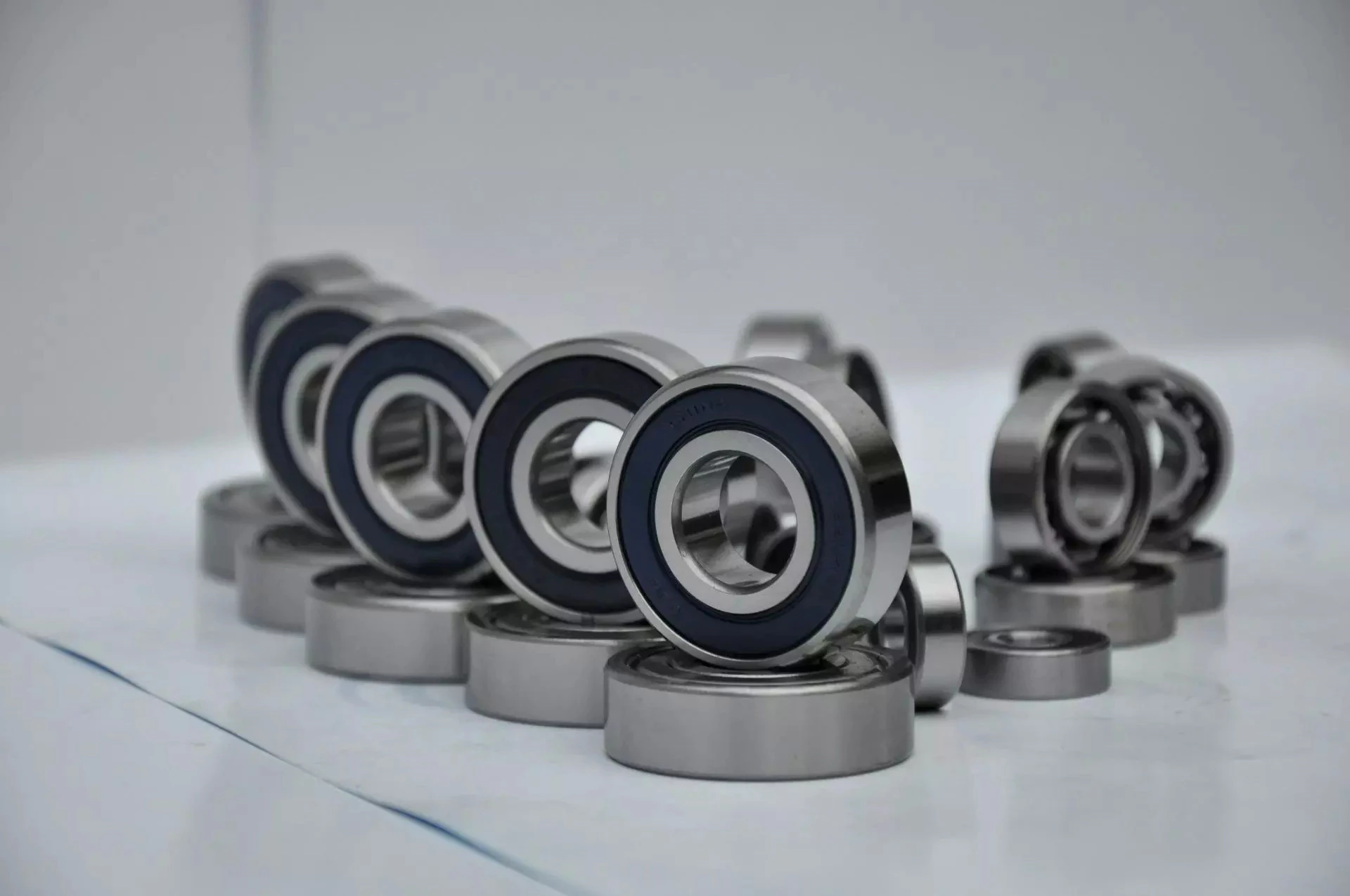
Single-row designs
Steel linear translation stages often use single-row designs for ball bearings. These types of bearings provide smooth linear travel and can withstand high loads. The material steel has a high modulus of elasticity and a high stiffness, as well as a lower thermal expansion than aluminum. For these reasons, steel is the material of choice for a ball bearing in a typical user environment. Single-row designs for ball bearings are also suitable for applications in humid or corrosive environments.
Single-row designs for ball bearings are available in a variety of sizes and are axially adjustable. They have a high radial capacity, but require relatively little space. Single-row deep groove ball bearings with snap rings are STN 02 4605 or R47, respectively. Bearings with snap rings are identified by a suffix such as NR. They may not have seals or shields installed.
These single-row angular contact ball bearings are capable of supporting axial and radial loads. In a two-raceway arrangement, the radial load on bearing A causes a radial load to act on bearing B. Both axial and radial forces are transmitted between single-row angular contact ball bearings, and the resulting internal force must be taken into account to calculate equivalent dynamic bearing loads P.
Single-row deep groove ball bearings are the most common type of ball bearings. These bearings are designed with only one row of rolling elements. The single-row design is simple and durable, which makes it ideal for high-speed applications. Single-row designs for ball bearings are also available in various bore sizes. They can also come in a variety of shapes and are non-separable. If you need a high-speed bearing, you may want to opt for a double-row design.
In addition to single-row designs for ball bearings, you can choose ceramic or steel ball bearings. Ceramic balls are considerably harder than steel balls, but they are not as hard as steel. Hence, ceramic bearings are stiffer than steel ball bearings, resulting in increased stress on the outer race groove and lower load capacity. This is a great benefit for those who need the bearings to be lightweight and strong.
The difference between single-row and double-row designs is in the way that the inner and outer ring are installed. A single-row design places the inner ring in an eccentric position relative to the outer ring. The two rings are in contact at one point, which causes a large gap in the bearing. The balls are then inserted through the gap. As a result, the balls are evenly distributed throughout the bearing, which forces the inner and outer rings to become concentric.
Deep-groove ball bearings are one of the most popular types of ball bearings. They are available in different designs, including snap-ring, seal and shield arrangements. The race diameter of a deep-groove ball bearing is close to the ball’s diameter. These types of bearings are suited for heavy loads, and their axial and radial support are excellent. Their main drawback is that the contact angle cannot be adjusted to accommodate a wide range of relative loads.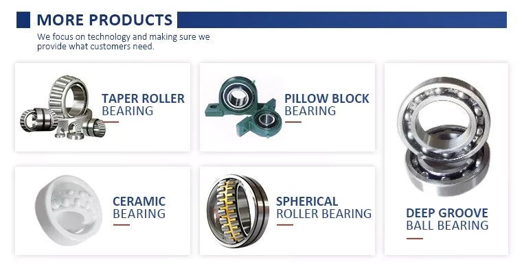
Ceramic hybrid ball bearings
Hybrid ball bearings with ceramic balls have numerous advantages. They feature improved kinematic behavior and require less lubrication. Consequently, they can reduce operating costs. Additionally, their low thermal expansion coefficient allows for smaller changes in contact angle and preload variations, and they can retain tolerances. Furthermore, ceramic hybrid ball bearings have significantly increased life spans compared to conventional steel-steel ball bearings, with up to 10 times the lifespan.
Although ceramic bearings can be used in automotive applications, many people believe that they’re a poor choice for bicycle hubs. They don’t reduce weight and only work well in high-rpm environments. As a result, many cyclists don’t even bother with ceramic-based bearings. However, both Paul Lew and Alan are of the opinion that ceramic bearings are best suited for industrial or medical equipment applications. Furthermore, Paul and Alan believe that they are ideal for high-altitude drone motors.
Another advantage of ceramic hybrid ball bearings is that they use less friction than conventional steel-based balls. They are also more durable, requiring less lubrication than steel-based bearings. Furthermore, the lower friction and rolling resistance associated with ceramic-based ball bearings means that they can last ten times longer than steel-based bearings. A ceramic-based hybrid ball bearing can be used for applications where speed and lubrication are critical.
Ceramic hybrid ball bearings feature both steel and silicon nitride balls. Silicon nitride balls have 50% more modulus of elasticity than steel balls and can improve accuracy and precision. Ceramic balls also have a smoother surface finish than steel balls, which reduces vibration and spindle deflection. These benefits result in increased speed and improved production quality. In addition to this, ceramic balls can also reduce the operating temperature, enhancing the work environment.
Hybrid bearings are a popular alternative to steel bearings. They have some benefits over traditional steel bearings, and are becoming a popular choice for engineered applications. Hybrid bearings are ideal for high speed machines. The material used to manufacture ceramic balls is a high-quality alloy, and is comparatively inexpensive. But you must understand that lubrication is still necessary for hybrid bearings. If you are not careful, you may end up wasting money.
These ball bearings can be used in many industries and applications, and they are widely compatible with most metals. The main advantage of hybrid ball bearings is that they are very durable. While steel balls tend to corrode and wear out, ceramic ball bearings can withstand these conditions while minimizing maintenance and replacement costs. The benefits of hybrid ball bearings are clear. So, consider switching to these newer types of ball bearings.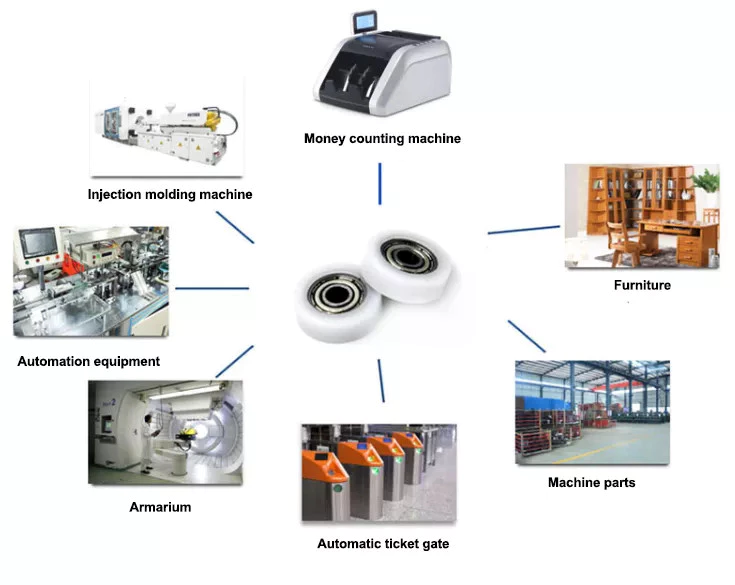
Self-aligning ball bearings
Self-aligning ball bearings are a good choice for many applications. They are a great alternative to traditional ball bearings, and they are ideal for rotating applications in which the shaft must move in several directions. They are also ideal for use in rotating parts where a tight tolerance is necessary. You can choose between two types: plain and flex shaft. Read on to find out which one will suit your needs.
Self-aligning ball bearings are designed with a higher axial load carrying capacity than single-row radial deep groove ball bearings. The amount of axial load carrying capacity is dependent upon the pressure angle. These bearings have a hollow raceway in the outer ring that allows the inner ring to pivot without friction. They are often used for high-speed applications. Because of their design, they are highly accurate.
Self-aligning ball bearings are radial bearings that feature two rows of balls in a spherical outer ring. They also feature two deep uninterrupted raceway grooves in the inner ring. Their unique features make them an excellent choice for applications where shaft deflection is a significant factor. Despite their small size, they have a high level of precision and can withstand heavy loads.
Self-aligning ball bearings can compensate for misalignment in shaft applications. The inner ring and ball assembly are positioned inside an outer ring containing a curved raceway. This spherical design allows the balls and cage to deflect and re-align around the bearing center. These bearings are also ideal for applications where shaft deflection is significant, such as in simple woodworking machinery.
Another type of self-aligning ball bearing uses a common concave outer race. Both balls and outer races automatically compensate for angular misalignment caused by machining, assembly, and deflections. Compared to spherical rollers, they have lower frictional losses than their spherical counterparts. Self-alignment ball bearings also have lower vibration levels compared to other types of bearings.
Self-aligning ball bearings operate in misaligned applications because their spherical outer raceway can accommodate misalignment. This design allows them to work in applications where shaft deflection or housing deformation is common. They are therefore more suitable for low to medium-sized loads. The only real drawback to self-aligning ball bearings is their price. If you need to purchase a self-aligning ball bearing for your next project, you can expect to pay around $1500.


China Professional Cnc Machining Laser Welding Assembly Parts Agriculture Machinery And Parts Agricultural Machinery Transmission agricultural parts suppliers
Situation: New
Guarantee: 6 Months
Applicable Industries: Manufacturing Plant, Farms, Building works , Strength & Mining
Weight (KG): 5 KG
Showroom Place: None
Movie outgoing-inspection: Supplied
Machinery Check Report: Supplied
Marketing Variety: Regular Item
Variety: SEATS
Use: Tractors
Item Identify: Custom made produced welding and stamping parts welding assembly
Content: Q235 or customized
Warmth treatment: Anxiety Relieving or as customer’s prerequisite
Area Treatment method: as customer’s requirement
tolerance: +/.05mm
Quality: one hundred%examined Prime
Package deal: Wood packing containers
Services: OEM ODM Assistance
Advantage: far more than fifteen several years Knowledge
Application: Agricultural equipment components
Packaging Specifics: Approach 1:Shrink movie+wooden boxMethod 2:cardboard box+palletMethod 3:Export wood caseMethod 4: custom made packing as customer’s need
Port: FOB HangZhou/ZheJiang
Goods Description
| OEM Services | ZHangZhoug Shengyi Equipment Co.,Ltd | |
| Available Content: | Brass,Copper,Carbon Metal,Stainless Steel,Steel Alloy,Aluminum Alloy,and many others. | |
| Heat Treatment: | Annealing,Quenching,Nitriding,Hardening,Tempering,Normalizing,and so forth. | |
| Tolerance: | As per drawing.(+/-.05mm,+/-.01mm) | |
| Surface Therapy: | Zinc-Plated,Nickel-Plated, Manual Pipe Decreasing Equipment Metal Tube table leg furnishings Swaging Device for Sale Chrome-Plated,Anodize,Phosphating,Chemical Blackening,Salt Bathtub Nitriding,etc. | |
| Guide Time: | 20-45Days Relies upon On Quantities and complexity | |
| Application: | Forklift,Crane,Practice,Truck,Lawnmower,Rail Road Euipment,healthcare system, industrial machine, automobile, electric powered equipment,Automation device,other industries,and many others, | |
| Payment Time period: | L/C at sightT/T thirty% deposit and well balanced 70% to spend before shipment. | |
| Port Of Loading: | ZheJiang or HangZhou, motor reducer whosale head gear boxing right angle spiral bevel gearbox for mixer concrete vertical reduction gearbox etc. | |
| Manufacturing Gear: | CNC Machining centre,CNC Lathe,Grinding Device,Milling Device,Sawing Machine,Welding Device,Hydraulic Press Equipment,Drilling and Tapping Machine,Gear Shaping Machine,and many others. | |
| Inspection Gear: | Electronic Penumatic Measuring Instrument,Three Coodinate Detection Products,Rockwell Hardness Tester,Electronic Ultrasonic Flaw Detector,Surface area Roughness Measuring Instrument,Leeb Hardness Tester,Cladding Measuring Instrument,Salt Spraying Tester,Gear Measurement Centre,and so on. | |
| QC: | one.Incoming materials will be checked prior to generation.2.Rigorous processing top quality manage.3.a hundred% inspection ahead of cargo.4.We are responsible for merchandise top quality to the stop person. | |
| Package: | Strategy 1:Carton box or corrugated cartonMethod 2:Wooden scenario or wood crateMethod 3: Iron basket or plastic basketMethod 4: Pallet | |
| Soon after-revenue Service: | We will comply with up items for clients and support to remedy troubles right after revenue. | |
| We are a OEM manufacturing unit to offer machinery elements according to the drawings oe samples.Modest purchase or sample order is suitable. | ||
Types of Splines
There are four types of splines: Involute, Parallel key, helical, and ball. Learn about their characteristics. And, if you’re not sure what they are, you can always request a quotation. These splines are commonly used for building special machinery, repair jobs, and other applications. The CZPT Manufacturing Company manufactures these shafts. It is a specialty manufacturer and we welcome your business.
Involute splines
The involute spline provides a more rigid and durable structure, and is available in a variety of diameters and spline counts. Generally, steel, carbon steel, or titanium are used as raw materials. Other materials, such as carbon fiber, may be suitable. However, titanium can be difficult to produce, so some manufacturers make splines using other constituents.
When splines are used in shafts, they prevent parts from separating during operation. These features make them an ideal choice for securing mechanical assemblies. Splines with inward-curving grooves do not have sharp corners and are therefore less likely to break or separate while they are in operation. These properties help them to withstand high-speed operations, such as braking, accelerating, and reversing.
A male spline is fitted with an externally-oriented face, and a female spline is inserted through the center. The teeth of the male spline typically have chamfered tips to provide clearance with the transition area. The radii and width of the teeth of a male spline are typically larger than those of a female spline. These specifications are specified in ANSI or DIN design manuals.
The effective tooth thickness of a spline depends on the involute profile error and the lead error. Also, the spacing of the spline teeth and keyways can affect the effective tooth thickness. Involute splines in a splined shaft are designed so that at least 25 percent of the spline teeth engage during coupling, which results in a uniform distribution of load and wear on the spline.
Parallel key splines
A parallel splined shaft has a helix of equal-sized grooves around its circumference. These grooves are generally parallel or involute. Splines minimize stress concentrations in stationary joints and allow linear and rotary motion. Splines may be cut or cold-rolled. Cold-rolled splines have more strength than cut spines and are often used in applications that require high strength, accuracy, and a smooth surface.
A parallel key splined shaft features grooves and keys that are parallel to the axis of the shaft. This design is best suited for applications where load bearing is a primary concern and a smooth motion is needed. A parallel key splined shaft can be made from alloy steels, which are iron-based alloys that may also contain chromium, nickel, molybdenum, copper, or other alloying materials.
A splined shaft can be used to transmit torque and provide anti-rotation when operating as a linear guide. These shafts have square profiles that match up with grooves in a mating piece and transmit torque and rotation. They can also be easily changed in length, and are commonly used in aerospace. Its reliability and fatigue life make it an excellent choice for many applications.
The main difference between a parallel key splined shaft and a keyed shaft is that the former offers more flexibility. They lack slots, which reduce torque-transmitting capacity. Splines offer equal load distribution along the gear teeth, which translates into a longer fatigue life for the shaft. In agricultural applications, shaft life is essential. Agricultural equipment, for example, requires the ability to function at high speeds for extended periods of time.
Involute helical splines
Involute splines are a common design for splined shafts. They are the most commonly used type of splined shaft and feature equal spacing among their teeth. The teeth of this design are also shorter than those of the parallel spline shaft, reducing stress concentration. These splines can be used to transmit power to floating or permanently fixed gears, and reduce stress concentrations in the stationary joint. Involute splines are the most common type of splined shaft, and are widely used for a variety of applications in automotive, machine tools, and more.
Involute helical spline shafts are ideal for applications involving axial motion and rotation. They allow for face coupling engagement and disengagement. This design also allows for a larger diameter than a parallel spline shaft. The result is a highly efficient gearbox. Besides being durable, splines can also be used for other applications involving torque and energy transfer.
A new statistical model can be used to determine the number of teeth that engage for a given load. These splines are characterized by a tight fit at the major diameters, thereby transferring concentricity from the shaft to the female spline. A male spline has chamfered tips for clearance with the transition area. ANSI and DIN design manuals specify the different classes of fit.
The design of involute helical splines is similar to that of gears, and their ridges or teeth are matched with the corresponding grooves in a mating piece. It enables torque and rotation to be transferred to a mate piece while maintaining alignment of the two components. Different types of splines are used in different applications. Different splines can have different levels of tooth height.
Involute ball splines
When splines are used, they allow the shaft and hub to engage evenly over the shaft’s entire circumference. Because the teeth are evenly spaced, the load that they can transfer is uniform and their position is always the same regardless of shaft length. Whether the shaft is used to transmit torque or to transmit power, splines are a great choice. They provide maximum strength and allow for linear or rotary motion.
There are three basic types of splines: helical, crown, and ball. Crown splines feature equally spaced grooves. Crown splines feature involute sides and parallel sides. Helical splines use involute teeth and are often used in small diameter shafts. Ball splines contain a ball bearing inside the splined shaft to facilitate rotary motion and minimize stress concentration in stationary joints.
The two types of splines are classified under the ANSI classes of fit. Fillet root splines have teeth that mesh along the longitudinal axis of rotation. Flat root splines have similar teeth, but are intended to optimize strength for short-term use. Both types of splines are important for ensuring the shaft aligns properly and is not misaligned.
The friction coefficient of the hub is a complex process. When the hub is off-center, the center moves in predictable but irregular motion. Moreover, when the shaft is centered, the center may oscillate between being centered and being off-center. To compensate for this, the torque must be adequate to keep the shaft in its axis during all rotation angles. While straight-sided splines provide similar centering, they have lower misalignment load factors.
Keyed shafts
Essentially, splined shafts have teeth or ridges that fit together to transfer torque. Because splines are not as tall as involute gears, they offer uniform torque transfer. Additionally, they provide the opportunity for torque and rotational changes and improve wear resistance. In addition to their durability, splined shafts are popular in the aerospace industry and provide increased reliability and fatigue life.
Keyed shafts are available in different materials, lengths, and diameters. When used in high-power drive applications, they offer higher torque and rotational speeds. The higher torque they produce helps them deliver power to the gearbox. However, they are not as durable as splined shafts, which is why the latter is usually preferred in these applications. And while they’re more expensive, they’re equally effective when it comes to torque delivery.
Parallel keyed shafts have separate profiles and ridges and are used in applications requiring accuracy and precision. Keyed shafts with rolled splines are 35% stronger than cut splines and are used where precision is essential. These splines also have a smooth finish, which can make them a good choice for precision applications. They also work well with gears and other mechanical systems that require accurate torque transfer.
Carbon steel is another material used for splined shafts. Carbon steel is known for its malleability, and its shallow carbon content helps create reliable motion. However, if you’re looking for something more durable, consider ferrous steel. This type contains metals such as nickel, chromium, and molybdenum. And it’s important to remember that carbon steel is not the only material to consider.
China supplier GM Belt Maker – Jiebao High Quality Neoprene Transmission Parts Fan Auto motorcycle Textile Garment Packaging Agricultural Machinery Synchronous Timing Beltt near me supplier
Product Description
Need TO KNOW Prior to Buying
Thank you for browsing our solution, we give you great top quality and right after-sale-support with competitive manufacturing unit rates.
All our item can be customized as for each your request or as per your drawings, please really feel freel to get in touch with us any time by e-Mail or WhatsApp / Wechat me for instantaneous respond to your inquiry.
The benefits of using pulleys
A pulley is a mechanical device that converts force into rotation. There are many advantages to using pulleys. Let’s take a look at a few of them. This article will describe the advantages, types, applications, and power sources of pulleys. You can then choose the pulley that best suits your specific needs. If you’re looking for a new tool to help you with a certain task, this article is for you.
Mechanical advantage
The mechanical advantage of a pulley can be defined as the ratio of applied force to the applied force. The mechanical advantage of a pulley can be calculated by considering several factors, including weight and friction. It can be calculated by the force applied per unit length of rope and the number of pulleys used. In a single-circuit system, the force required to lift a heavy object is equal to the user’s body weight.
The mechanical advantage of a pulley can be realized by comparing it to a seesaw. Both uses of rope are suitable for lifting objects. A rope four times heavier than a kilo is four times as effective. Because the forces on both sides of the pulley are equal, a small force is enough to move a large weight a short distance. The same force can be applied to a large mass to lift it several meters.
After introducing the concept of mechanical advantage, learners will practice using the pulley system. In addition to testing the pulley system, they should also calculate its mechanical advantage. Using either the instructor-provided handout or the learner’s workbook, students will determine how easily the pulley system functions. Once they have completed the test, they can discuss their results and how the system can be improved. These courses are best completed as part of a mini-unit or as a standalone main course.
The mechanical advantage of the pulley system is proportional to the number of rope loops. This circuit requires the same force as the dual circuit to lift heavy objects. A single lap requires only a third of the force to lift a double lap, while three laps require almost half the energy required for a single lap. The mechanical advantage of the pulley system becomes constant as the number of cycles increases.
The 3:1 Mechanical Advantage system feels like lifting a 300-pound load with three feet of rope. The three-foot-long rope moves the load one foot high. Understanding the mechanical advantages of pulleys is critical for rescuers when trying to create the perfect pulley system. Ideally, the pulley system will be anchored to a nearby rock, tree, pole or person – if the weight is not too heavy.
Types of pulleys
There are several types of pulleys. V-belt pulleys are the type commonly used in vehicles and electric motors. “V” pulleys require a “V” belt, and some even have multiple V grooves. “V” pulleys are often used in heavy duty applications for power transmission because they reduce the risk of power slippage.
Composite pulleys combine the properties of fixed and movable pulleys. Compound pulleys are able to change the direction of force while requiring relatively low force to move even the heaviest loads. Mechanical advantage is a measure of the effectiveness of a machine or equipment. It can be divided into three categories: force, distance and mechanics. Once you understand how each type works, you can design complex machines.
Fixed pulleys: These pulleys are the most basic type of pulleys. They use ropes and slotted wheels to move with the lifted object. Because they are so simple to set up, lifting heavy objects is a breeze. Although the moving object feels light, it is actually heavier than it actually is. These pulleys are used in construction cranes, utility elevators and many different industries.
Compound Pulley System: A pulley pulley is a combination of two fixed pulleys and one movable pulley. Compound pulley systems are effective for moving heavy objects because they have the largest force multipliers and are flexible enough to change the direction of the force as needed. Composite pulley systems are commonly used in rock climbing, theater curtains and sailing. If you’re looking for a pulley system, you can start by evaluating the types of pulleys and their uses.
Construction Pulleys: These are the most basic types of pulleys and have wheel rails. These pulleys can be lifted to great heights and attached to chains or ropes. They allow workers to access equipment or materials from greater heights. They are usually mounted on wheels with axles and secured with ropes. They are essential tools for construction workers. There are many different types of pulleys out there.
energy source
Belts and pulleys are mechanical devices used to transmit energy and rotational motion. The belt is connected to the rotating part of the energy source, and the pulley is mounted on the other. One pulley transmits power to the other, while the other changes the direction of the force. Many devices use this combination, including automobiles, stationary generators, and winches. It is used in many home applications, from conveyors to treadmills. Pulleys are also used for curtains in theater halls.
Pulley systems are an essential part of modern industry and everyday life. Pulleys are used in elevators, construction sites and fitness equipment. They are also used in belt-driven generators as backup power. Despite their simple and seemingly humble beginnings, they have become a versatile tool. From lifting heavy objects to guiding wind turbines, pulley systems are widely used in our daily lives.
The main reason why pulleys are so popular is the mechanical advantage they offer. They can lift a lot of weight by applying very little force over longer distances. For example, a small motor can pull 10 meters of cable, while a large motor can pull 1 meter. Also, the work done is equal to the force times the distance traveled, so the energy delivered to the large motor is the same.
The power source for the pulley system can be cables, belts or ropes. The drive element in a pulley system is usually a rope or cable. A belt is a loop of flexible material that transmits motion from one pulley to another. The belt is attached to the shaft and a groove is cut in the pulley. The belt then transfers energy from one pulley to the other through the system.
application
A pulley is a mechanical device used to lift heavy objects. They reduce the amount of work required to lift heavy objects and are an excellent choice for many applications. There are several different applications for pulleys, including elevators, grinders, planters, ladder extensions, and mountaineering or rock climbing. Let’s take a look at some of the most popular uses for pulleys in modern society. These include:-
A pulley is a mechanical device that changes force. To use, you wrap the rope around it and pull down to lift the object. While this device is very useful, a major limitation of using pulleys is that you still have to apply the same force to lift the object as you would without the pulleys. This is why people use pulleys to move large objects like furniture and cars.
In addition to lifting heavy objects, pulleys are used in elevators, flagpoles and wells. These systems allow people to move heavy objects without straining their backs. Many other examples of pulleys in the home include garage doors, flagpoles, and elevators. They also help raise and lower flagpoles, which can reach several stories high.
There are two basic types of pulleys: movable and fixed. Fixed pulleys are attached to a ceiling or other object using two ropes. Modern elevators and construction cranes use movable pulleys, as do some weight machines in gyms. Composite pulleys combine movable and fixed pulleys to minimize the force required to move heavy objects.
Another type of fixed pulley is the flagpole. A flagpole can support a country, organization, or anything else that needs to be lifted. A taller flagpole creates a prouder moment for those who support it. The operation of the rope and pulley mechanism is very simple. The user simply attaches the flag to the rope, pulls the pulley, and he or she can watch the flag rise and unfold.
China OEM Farm Machinery Agricultural Machinery Tractor Cultivator Harvester and Separator Spare Parts Cast Iron Machine Piece Parts with Best Sales
Solution Description
1
Name: farm machinery agricultural machinery tractor cultivator harvester and separator spare elements cast iron machine piece parts
Substance: Casting Iron or Metal
Min purchase: 1000 pcs
Packing: export normal packing
Tailored manufacturing is available as your drawings or sample.
2
About quality
We insist that the survival of the organization should depend on the merchandise quality continuous improvement, without having which we can’t endure for lengthy.
Our solution top quality manage system
Top quality control involves the inspection and control of incoming components, manufacturing method and finished goods.
one Firstly, metallurgical microscope analysis is done on randomly sampled incoming materials to guarantee that the chemical composition satisfies the production needs.
2 Then, for the duration of the production method, there are QC staff to conduct timely place checks to guarantee that the merchandise is cost-free of defects during the producing method and to coordinate and managing of any abnormal quality problems that may crop up.
three The closing stage in the production approach is a magnetic particle detector for metal areas to detect hidden cracks or other defects.
4 All the finished steel components is sampled in proportion and sent to the laboratory for numerous mechanical home tests and dimensional measurements, and the floor quality is manually one hundred% inspected.
5 About the good quality management program, we strictly have out method administration in accordance with ISO9001 and TS16949 quality standards and 5S lean manufacturing management is implemented on the creation web site.
3
Our Positive aspects:
Brand name
Our father or mother business, HiHangZhou Group, is a entire world-renowned high-conclude machinery production company with forty domestic subsidiaries and branches and 8 international manufacturing crops. Has prolonged-term encounter and very good popularity in cooperation with entire world-renowned enterprises.
Technology
We have a complete generation method and equipment study and growth capabilities for ferrous metals forming. More than 25 a long time of creation knowledge in forging tools and casting equipment manufacturers, make us much more thoroughly get all the efficiency of each equipment. One particular-third of our firm’s personnel are technician and R&D personnel, guaranteeing that substantial-high quality products are created with higher performance.
Support
We can provide personalized and standard production services with numerous manufacturing approach integrations. The high quality and shipping and delivery of goods can be totally certain, and the ability to converse speedily and efficiently.
Culture
The exclusive corporate lifestyle can give total engage in to the prospective of individuals and supply a sturdy vitality for the sustainable advancement of the firm.
Social responsibility
Our business strictly implements reduced-carbon environmental safety, power-conserving and emission-reduction generation, and is a benchmark company in regional location.
5
Business Culture
Our Vision
To turn into 1 of the foremost companies
Our Mission
To become a system for workers to comprehend their dream
To turn into 1 of the transforming and upgrading pacemaker of Chinese enterprises
To established the national makes with satisfaction
Our Belief
Strive to develop the business into an perfect system for entrepreneurs to understand their self-worth and contribute to the society
Values
Improvement is innovation, every person can innovate
innovation impressed and failures tolerated
4
FAQ
one.
Q: Are you a trading firm or a manufacturer?
A: Obviously we are a manufacturer of forging merchandise, casting goods and also have a substantial level of machining capabilities.
2.
Q: What sequence items do your have?
A: We are largely engaged in forming processing of ferrous metals, like processing by casting , forging and machining. As you know, such machinery parts can be observed in various industries of products producing.
three
Q: Do you give samples? is it free of charge?
A: Yes, we commonly provide samples in accordance to the traditional practice, but we also require buyers to supply a freight shell out-by-account number to present mutual sincerity of cooperation.
4
Q: What is your least purchase amount?
A: Sure, we need all worldwide orders to have an bare minimum order quantity. The amount is up to the actual items function or house these kinds of as the substance, bodyweight, design and so on.
5
Q: What is the lead time?
A: Normally our forging items and casting goods need to have to make new dies or molds, the time of producing new dies or molds and samples inside of 30-forty five days, and the large batch production time in 30-45 days. it really is also in accordance to the elements structural complexity and quantity.
six
Q: What sorts of payment approaches do you acknowledge?
A: You can make the payment by T/T or L/C. 30% deposit in advance, 70% stability against the copy of B/L.
Certification
| Process | Sand Casting and CNC machining | ||||||
| Material | Grey Iron , Ductile Iron, Carbon Steel | ||||||
| Weight | 0.1Kgs~100Kgs | ||||||
| Testing instrument | composition testing | Spectrometer, Metallographic microscope | |||||
| Performance testing | Hardness tester, Tensile testing machine | ||||||
| Size Measuring | Vernier Caliper, Depth Caliper, feeler gauge,Thread Gauge , Height Gauge | ||||||
| Roughness | Ra0.8~Ra6.3 | ||||||
| Machining Equipment | CNC Center , CNC Machines, Turning, Drilling, Milling, Boring machine,Grinding Machines, | ||||||
| Wire EDM,Laser Cutting&Welding, Plasma Cutting &Welding, EDM etc. | |||||||
| Quality control | Sampling inspection of raw materials and semi-finished products, 100% Inspection of finished products | ||||||
| Surface Treatment | Sand Blast , Painting, Powder Coating, Galvanized , Hot Galvanized | ||||||
| Production Capacity | 60000T / Years | ||||||
| Lead Time | Normally 30 – 45 Days. | ||||||
| Payment Terms | T/T , L/C | ||||||
| Material Standard | ASTM , AISI , DIN , BS, JIS, GB, | ||||||
| Certification | ISO9001:2008, IATF16949:2016 | ||||||
What Are Worm Gears and Worm Shafts?
If you’re looking for a fishing reel with a worm gear system, you’ve probably come across the term ‘worm gear’. But what are worm gears and worm shafts? And what are the advantages and disadvantages of worm gears? Let’s take a closer look! Read on to learn more about worm gears and shafts! Then you’ll be well on your way to purchasing a reel with a worm gear system.
worm gear reducers
Worm shaft reducers have a number of advantages over conventional gear reduction mechanisms. First, they’re highly efficient. While single stage worm reducers have a maximum reduction ratio of about five to sixty, hypoid gears can typically go up to a maximum of one hundred and twenty times. A worm shaft reducer is only as efficient as the gearing it utilizes. This article will discuss some of the advantages of using a hypoid gear set, and how it can benefit your business.
To assemble a worm shaft reducer, first remove the flange from the motor. Then, remove the output bearing carrier and output gear assembly. Lastly, install the intermediate worm assembly through the bore opposite to the attachment housing. Once installed, you should carefully remove the bearing carrier and the gear assembly from the motor. Don’t forget to remove the oil seal from the housing and motor flange. During this process, you must use a small hammer to tap around the face of the plug near the outside diameter of the housing.
Worm gears are often used in reversing prevention systems. The backlash of a worm gear can increase with wear. However, a duplex worm gear was designed to address this problem. This type of gear requires a smaller backlash but is still highly precise. It uses different leads for the opposing tooth face, which continuously alters its tooth thickness. Worm gears can also be adjusted axially.
worm gears
There are a couple of different types of lubricants that are used in worm gears. The first, polyalkylene glycols, are used in cases where high temperature is not a concern. This type of lubricant does not contain any waxes, which makes it an excellent choice in low-temperature applications. However, these lubricants are not compatible with mineral oils or some types of paints and seals. Worm gears typically feature a steel worm and a brass wheel. The brass wheel is much easier to remodel than steel and is generally modeled as a sacrificial component.
The worm gear is most effective when it is used in small and compact applications. Worm gears can greatly increase torque or reduce speed, and they are often used where space is an issue. Worm gears are among the smoothest and quietest gear systems on the market, and their meshing effectiveness is excellent. However, the worm gear requires high-quality manufacturing to perform at its highest levels. If you’re considering a worm gear for a project, it’s important to make sure that you find a manufacturer with a long and high quality reputation.
The pitch diameters of both worm and pinion gears must match. The two worm cylinders in a worm wheel have the same pitch diameter. The worm wheel shaft has two pitch cylinders and two threads. They are similar in pitch diameter, but have different advancing angles. A self-locking worm gear, also known as a wormwheel, is usually self-locking. Moreover, self-locking worm gears are easy to install.
worm shafts
The deflection of worm shafts varies with toothing parameters. In addition to toothing length, worm gear size and pressure angle, worm gear size and number of helical threads are all influencing factors. These variations are modeled in the standard ISO/TS 14521 reference gear. This table shows the variations in each parameter. The ID indicates the worm shaft’s center distance. In addition, a new calculation method is presented for determining the equivalent bending diameter of the worm.
The deflection of worm shafts is investigated using a four-stage process. First, the finite element method is used to compute the deflection of a worm shaft. Then, the worm shaft is experimentally tested, comparing the results with the corresponding simulations. The final stage of the simulation is to consider the toothing geometry of 15 different worm gear toothings. The results of this step confirm the modeled results.
The lead on the right and left tooth surfaces of worms is the same. However, the lead can be varied along the worm shaft. This is called dual lead worm gear, and is used to eliminate play in the main worm gear of hobbing machines. The pitch diameters of worm modules are equal. The same principle applies to their pitch diameters. Generally, the lead angle increases as the number of threads decreases. Hence, the larger the lead angle, the less self-locking it becomes.
worm gears in fishing reels
Fishing reels usually include worm shafts as a part of the construction. Worm shafts in fishing reels allow for uniform worm winding. The worm shaft is attached to a bearing on the rear wall of the reel unit through a hole. The worm shaft’s front end is supported by a concave hole in the front of the reel unit. A conventional fishing reel may also have a worm shaft attached to the sidewall.
The gear support portion 29 supports the rear end of the pinion gear 12. It is a thick rib that protrudes from the lid portion 2 b. It is mounted on a bushing 14 b, which has a through hole through which the worm shaft 20 passes. This worm gear supports the worm. There are two types of worm gears available for fishing reels. The two types of worm gears may have different number of teeth or they may be the same.
Typical worm shafts are made of stainless steel. Stainless steel worm shafts are especially corrosion-resistant and durable. Worm shafts are used on spinning reels, spin-casting reels, and in many electrical tools. A worm shaft can be reversible, but it is not entirely reliable. There are numerous benefits of worm shafts in fishing reels. These fishing reels also feature a line winder or level winder.
worm gears in electrical tools
Worms have different tooth shapes that can help increase the load carrying capacity of a worm gear. Different tooth shapes can be used with circular or secondary curve cross sections. The pitch point of the cross section is the boundary for this type of mesh. The mesh can be either positive or negative depending on the desired torque. Worm teeth can also be inspected by measuring them over pins. In many cases, the lead thickness of a worm can be adjusted using a gear tooth caliper.
The worm shaft is fixed to the lower case section 8 via a rubber bush 13. The worm wheel 3 is attached to the joint shaft 12. The worm 2 is coaxially attached to the shaft end section 12a. This joint shaft connects to a swing arm and rotates the worm wheel 3.
The backlash of a worm gear may be increased if the worm is not mounted properly. To fix the problem, manufacturers have developed duplex worm gears, which are suitable for small backlash applications. Duplex worm gears utilize different leads on each tooth face for continuous change in tooth thickness. In this way, the center distance of the worm gear can be adjusted without changing the worm’s design.
worm gears in engines
Using worm shafts in engines has a few benefits. First of all, worm gears are quiet. The gear and worm face move in opposite directions so the energy transferred is linear. Worm gears are popular in applications where torque is important, such as elevators and lifts. Worm gears also have the advantage of being made from soft materials, making them easy to lubricate and to use in applications where noise is a concern.
Lubricants are necessary for worm gears. The viscosity of lubricants determines whether the worm is able to touch the gear or wheel. Common lubricants are ISO 680 and 460, but higher viscosity oil is not uncommon. It is essential to use the right lubricants for worm gears, since they cannot be lubricated indefinitely.
Worm gears are not recommended for engines due to their limited performance. The worm gear’s spiral motion causes a significant reduction in space, but this requires a high amount of lubrication. Worm gears are susceptible to breaking down because of the stress placed on them. Moreover, their limited speed can cause significant damage to the gearbox, so careful maintenance is essential. To make sure worm gears remain in top condition, you should inspect and clean them regularly.
Methods for manufacturing worm shafts
A novel approach to manufacturing worm shafts and gearboxes is provided by the methods of the present invention. Aspects of the technique involve manufacturing the worm shaft from a common worm shaft blank having a defined outer diameter and axial pitch. The worm shaft blank is then adapted to the desired gear ratio, resulting in a gearbox family with multiple gear ratios. The preferred method for manufacturing worm shafts and gearboxes is outlined below.
A worm shaft assembly process may involve establishing an axial pitch for a given frame size and reduction ratio. A single worm shaft blank typically has an outer diameter of 100 millimeters, which is the measurement of the worm gear set’s center distance. Upon completion of the assembly process, the worm shaft has the desired axial pitch. Methods for manufacturing worm shafts include the following:
For the design of the worm gear, a high degree of conformity is required. Worm gears are classified as a screw pair in the lower pairs. Worm gears have high relative sliding, which is advantageous when comparing them to other types of gears. Worm gears require good surface finish and rigid positioning. Worm gear lubrication usually comprises surface active additives such as silica or phosphor-bronze. Worm gear lubricants are often mixed. The lubricant film that forms on the gear teeth has little impact on wear and is generally a good lubricant.
China Custom CNC Machinery Machined Machining Part for Car/Motorcycle/Agricultural/Aerospace Parts near me factory
Solution Description
HangZhou JIAHAO XINDA Technological innovation CO LTD
Aluminum machining anodized surface therapy cnc mahine components China product
Product Application Details:
FAQ:
Q: How Can I get a quotation?
A: Please give 2d(or 3D) files or samples.
Draw structure:IGS,Stage,STP, JPEG,PDF,DWG,DXF,CAD and so on.
Q: What is your MOQ?
A: No MOQ minimal, trial purchase before mass creation is welcomed.
Q: What is your machining scope?
A: CNC or non CNC machining(consist of turning and milling), grinding, punching, laser printing(logo) /engraving, Wire EDM service.
Q:What about good quality control?
A.: Self-inspection in each and every method by the generation operator.
Defective rate be managed within 1% even reduce.
Q: What is the after-product sales?
A: We will free remake components or return payment if are positive that it is our error.
This is our commitment. Quality is our culture!
|
Origin Country |
Shenzhen,China |
|
Trade terms |
EXW,FOB |
|
Description |
The Best Precision Metal Case Machining Services Cnc machine parts |
|
Machined Material |
1). Aluminum: AL 6061-T6, 6063, 7075-T etc 3). Steel: 45#,Q235, Q345B |
|
Surface Treatment |
Sandblasting,Anodize color,Zinc/Nickl Plating,Polish, |
|
Processing Technology |
CNC machining parts,turning/milling process |
|
MOQ |
1pcs |
|
Lead Time |
Sample: 3-5 days. Mass Production: within 10-25 days after receiving the deposit. |
|
Package |
*a. pp bags + carton or wooden case *b. according to customers’ requirements *c.negotiable |
|
Payment Terms |
*T/T : 50% deposit balanced 50% before shipping
|
|
Service |
*Fast deivery *Reliable and cheap freight company *Good after-sale services |
###
|
Industry Focus |
Appliance/ Automotive/tooling fixtures/mold tools Electronics/ Industrial/ medical equipments,food machinery aerospace/solar and electronic ,photoelectronic communication,house hold appliances,highways,barrier gate
|
|
Lead Times Available
|
Max: 2 Weeks (On Initial Order) Prototype Available |
|
Tolerance |
±0.001mm
|
###
| Product Show |
###
| Company Profile |
###
| Shenzhen Jiahao Xinda Technology Co., Ltd. established in 2009, is a pure-play enterprise dedicated to developing and manufacturing nonstandard machine parts and equipment processing, covering an area of 2600 square meters. Our company is located in Fuyong Town, Bao’an District, Shenzhen City.
We have over 40 professional manufacturing and possessing equipment, which includes CNC, milling machine, lathe machine, precision grinding machine and line cutting machine. And there are various testing equipment imported with high precision in our quality department, including 3D and 2.5D measuring equipment,altimeter and hardness tester. At present, our knock-out products mainly include precision automatic equipment parts, tooling fixtures,mobile phone accessories, automotive parts, medical equipment parts,aerospace, solar and electronic equipment, photoelectric communication, office automation, industrial equipment, laser equipment, household appliances, highways,and other industries. |
###
| Certification |
###
| Exhibition |
###
| Packing& Shipping |
|
Origin Country |
Shenzhen,China |
|
Trade terms |
EXW,FOB |
|
Description |
The Best Precision Metal Case Machining Services Cnc machine parts |
|
Machined Material |
1). Aluminum: AL 6061-T6, 6063, 7075-T etc 3). Steel: 45#,Q235, Q345B |
|
Surface Treatment |
Sandblasting,Anodize color,Zinc/Nickl Plating,Polish, |
|
Processing Technology |
CNC machining parts,turning/milling process |
|
MOQ |
1pcs |
|
Lead Time |
Sample: 3-5 days. Mass Production: within 10-25 days after receiving the deposit. |
|
Package |
*a. pp bags + carton or wooden case *b. according to customers’ requirements *c.negotiable |
|
Payment Terms |
*T/T : 50% deposit balanced 50% before shipping
|
|
Service |
*Fast deivery *Reliable and cheap freight company *Good after-sale services |
###
|
Industry Focus |
Appliance/ Automotive/tooling fixtures/mold tools Electronics/ Industrial/ medical equipments,food machinery aerospace/solar and electronic ,photoelectronic communication,house hold appliances,highways,barrier gate
|
|
Lead Times Available
|
Max: 2 Weeks (On Initial Order) Prototype Available |
|
Tolerance |
±0.001mm
|
###
| Product Show |
###
| Company Profile |
###
| Shenzhen Jiahao Xinda Technology Co., Ltd. established in 2009, is a pure-play enterprise dedicated to developing and manufacturing nonstandard machine parts and equipment processing, covering an area of 2600 square meters. Our company is located in Fuyong Town, Bao’an District, Shenzhen City.
We have over 40 professional manufacturing and possessing equipment, which includes CNC, milling machine, lathe machine, precision grinding machine and line cutting machine. And there are various testing equipment imported with high precision in our quality department, including 3D and 2.5D measuring equipment,altimeter and hardness tester. At present, our knock-out products mainly include precision automatic equipment parts, tooling fixtures,mobile phone accessories, automotive parts, medical equipment parts,aerospace, solar and electronic equipment, photoelectric communication, office automation, industrial equipment, laser equipment, household appliances, highways,and other industries. |
###
| Certification |
###
| Exhibition |
###
| Packing& Shipping |
What is a bushing?
What is a bushing? Basically, bushings are spherical or spherical bearings for machines with sliding or rotating shaft assemblies. Due to their excellent load-carrying capacity and anti-friction properties, these bushings are used in almost all industrial applications. This makes them useful in industries such as construction, mining, agriculture, transportation, hydropower, food processing and material handling.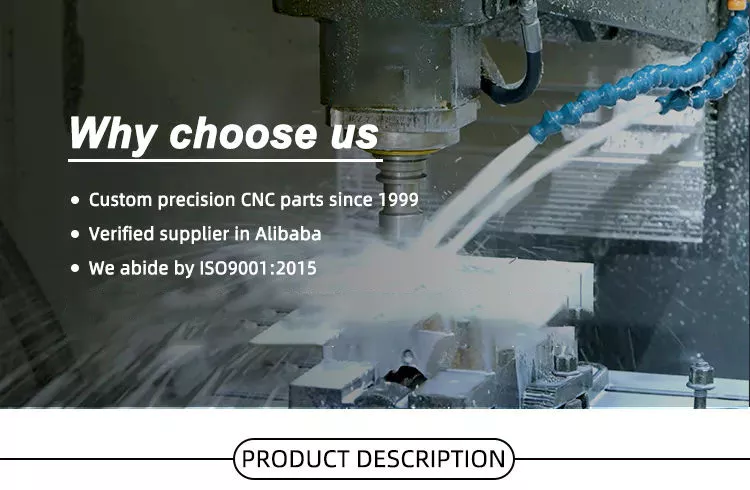
Shell information
The demand for bushings is closely related to the global transformer market. Growing renewable energy sources and high replacement rates of aging grid infrastructure are driving the global demand for transformer bushings. Increased urbanization is another factor driving the demand for transformer bushings. Among global regions, Asia Pacific is the largest market for medium voltage transformer bushings. The following section provides a detailed analysis of the market.
Bulk-type bushings are used for lower voltage ratings and consist of a center conductor stud or tube and an insulator housing. They are available in dry or oil filled versions, and their oil content is shared with the transformer main tank. However, the trend is slowly turning towards RIP bushings. Regardless of how different types of bushings are used, it is important to understand the difference between them.
A recent CZPT survey indicated that bushings account for 17% of all transformer failures. Among them, 30% caused fire accidents and 10% caused explosions. This is not a small risk, especially for such important electrical components as transformers. Because casing is so important, utilities are increasingly looking to preventative maintenance. However, this requires continuous monitoring of the bushing and its insulation. There are many benefits to using online condition monitoring.
One of the main benefits of locating and replacing faulty bushings is improved operability and safety. If you notice that your car is unstable in the corners, your bushings are worn. Anti-roll bar bushings can also be a sign of bushing damage. Do not ignore these warning signs as they can have dangerous consequences. To avoid these potential problems, make sure to get your vehicle serviced as soon as you notice any of these symptoms.
Be sure to park your vehicle on a level surface before you start changing your car bushings. You may need to unlock the hood latch and apply the brakes before continuing. Then, open the valve cover. This will allow you to see the engine area and bushings. You should also check that the wheels are not moving and avoid placing sharp objects in the engine bay. If you have time, open the hood and if you can see the bushings, turn on the headlights.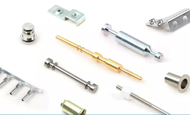
type
There are various types of bushings, each serving a different purpose. Oil-filled types are the most common and are designed for vertical installations. On the other hand, the embedded ferrule can accommodate the connection to the wire leads in the lower end of the ferrule. This feature significantly reduces the length of the sump end of the casing, but also adds additional complexity and cost.
There are two basic types of bushings. The first is a solid pour and the second is a capacitive graded variety. Solid cast bushings are typically used for low voltage transformer windings, while gas insulated bushings are insulated with pressurized gas. Gas-insulated bushings are also used in SF6 circuit breakers. If you are in the market for a new bushing, be sure to consider its cantilever strength and design.
Electrical bushings are an important part of various electrical equipment. They help carry high-voltage current through the enclosure and act as an insulator between a live conductor and a metal body at ground potential. Bulk-type bushings consist of a central conductive rod (usually copper or aluminum) and an insulator (silicone rubber compound or composite resin) surrounding the rod.
Transformers require transformer bushings. The construction and materials used in the bushing play a key role in the durability and longevity of the transformer. Transformers with weak bushings can fail, causing extensive damage. Moisture or voids can cause insulation breakdown, resulting in extensive electrical damage. Appropriate materials and optimized construction can reduce electric field stress and extend the life of the bushing.
Capacitor grading bushings are more expensive and are used in almost all high voltage systems. They use a conductive layer within the insulating layer between the center conductor and the insulator. Different manufacturers use different materials to produce these bushings. Earlier, capacitor grading bushings were made of concentric ceramic cylinders with metallized surfaces. They are also made from laminated cardboard tubes with conductive layers.
Function
A bushing is a support member that performs its function by acting as a washer and reducing noise and vibration. Bushings are used in valve covers and are made of corrosion-resistant materials to perform these functions. These products can be found in all types of machinery from cars to airplanes. Below are some common uses for bushings. Read on to discover more. Here are some of the most important features of the shell.
Electrical bushings transmit electricity. They can be used in circuit breakers, transformers, power capacitors and shunt reactors. The conductors of the bushing can be built directly into the bushing or through the bushing. Both current and voltage represent electricity. The bushing must have insulation capable of withstanding the voltage and its current-carrying conductors must be capable of carrying the rated current without overheating the adjacent insulation.
The bushing wraps around the stem, which is a relatively simple replacement part. It is a hardened part that prevents leaks and improves sealing. Plus, its low-cost replacement makes it a very easy-to-machine part. Bushings are also used in valves for guiding purposes. These two features make bushings an important part of many machines and applications. So, learn more about them.
Copper and brass are commonly used bushing materials. They have high compressive strength and high surface pressure. This material is suitable for bearings in low speed situations and heavy duty applications. Copper and brass are the most common types of casings, and they are both made in China. They are all relatively inexpensive and are available in a variety of materials and sizes. If you are considering purchasing a casing, keep in mind that it must meet national standards.
cost
Whether you’re looking for a replacement bushing for your rear suspension or just need to replace the fork, you have a few different options. The two main types of bushings are coated and uncoated. If you want to save money on bushing replacements, you should consider getting a cheaper lower fork. Whether you’re replacing bushings to improve ride quality or prevent damage to your wheel loader, you’ll find a bushing replacement option that fits your budget.
While most cars are compatible with bushings, some iconic parts from premium brands like BMW and Mercedes require special tools to replace. If you are not confident in your mechanical abilities, consider hiring a mechanic to do it. Mechanical replacement bushings typically range from $200 to $500. If you’re comfortable with mechanics and have some mechanical knowledge, you can save money by trying the job yourself. For example, control arm bushings range in price from $20 to $80. It is important to check the alignment after replacing the bushing to avoid further damage.
Control arm bushing replacements are usually relatively inexpensive, but you may need to replace several at the same time. You should check the prices of several mechanics before making a decision. You can easily save between $50 and $100 by comparing quotes. Plus, you’ll save a lot of money by finding the right mechanic for the job. You can also use an online comparison tool to compare prices. You can find a mechanic that suits your needs at an affordable price.
Control arm bushings are also an inexpensive way to replace parts of a car’s front or rear suspension. Typically, control arm bushings are made of two metal cylinders covered with a thick layer of rubber. They wear out due to accidents, potholes and off-roading. They are mounted with a bolt that goes through the inner barrel. It is important to replace these bushings as often as needed to improve operation.